
Welcome to CivilGEO Knowledge Base
Welcome to CivilGEO Knowledge Base
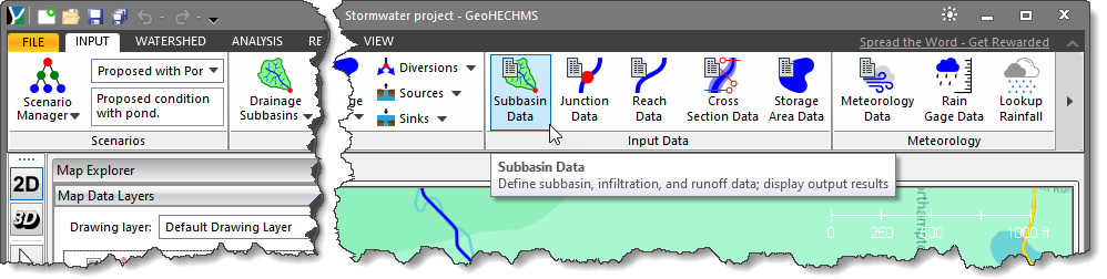
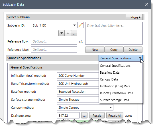
Subbasins define the drainage area polygons that produce runoff to the other elements in the model. In GeoHECHMS, the Subbasin Data command allows users to add new subbasin and edit subbasin data in a project.
Follow the steps below to view or modify the subbasin data:
 Alternatively, the user can either double-click on the subbasin polygon from the Map View or choose the Subbasin Data command from the Drainage Subbasins dropdown menu of the Input ribbon menu.
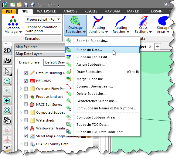
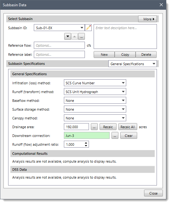
The following sections describe the Subbasin Data command and how to interact with the above dialog box.
The Select Subbasin section allows the user to select the subbasin for defining the subbasin data. The user can create a new subbasin, copy existing subbasin data to a new subbasin, and delete a subbasin. In addition, the user can navigate between subbasins and enter a description detailing the defined subbasin.
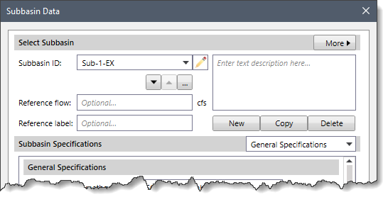
The following options are provided in this section:
![[Accept Changes] button](/wp-content/uploads/sites/25/2023/03/Subbasin-Data-Command-Image-5.png)
The following sections describe the subbasin. Click on the dropdown selector at the Subbasin Specifications entry to display the various data panels that define the subbasin data.
This panel allows the user to define the infiltration, runoff, baseflow, surface storage, and canopy methods to be used for the current subbasin.
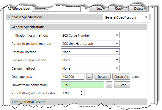
Note that the infiltration, runoff, baseflow, surface storage, and canopy methods are defined for the project in the Scenario Manager, which will be displayed automatically in the corresponding dropdown entries. However, the user can change the desired method for the selected subbasin from this dialog box. Refer to this article in our knowledge base to learn how to use the Scenario Manager dialog box.
The following options are provided in this data panel:
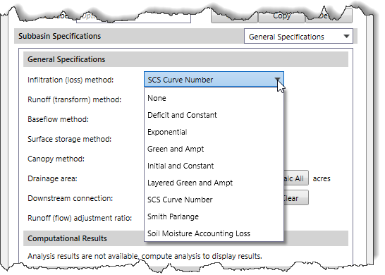 Refer to this article in our knowledge base to learn about various infiltration methods and how to use them to compute surface runoff.
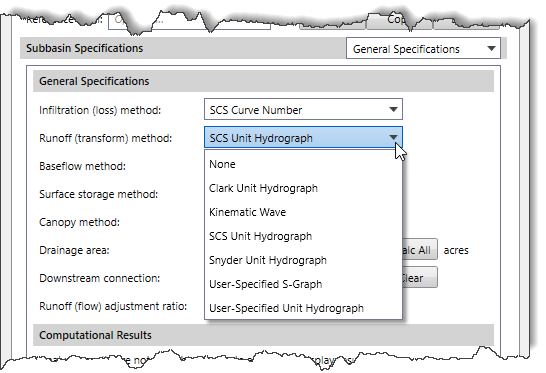 Refer to this article in our knowledge base to learn about various runoff methods and how to use them to compute surface runoff.
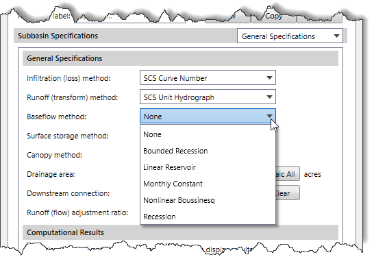 Refer to this article in our knowledge base to learn about various baseflow methods and how to use them to compute surface runoff.
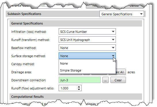 Refer to this article in our knowledge base to learn about various surface storage methods and how to use them to compute surface runoff.
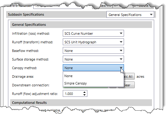 Refer to this article in our knowledge base to learn about various canopy methods and how to use them to compute surface runoff.
This section allows the user to see the analysis results for the current subbasin that was computed by HEC-HMS.
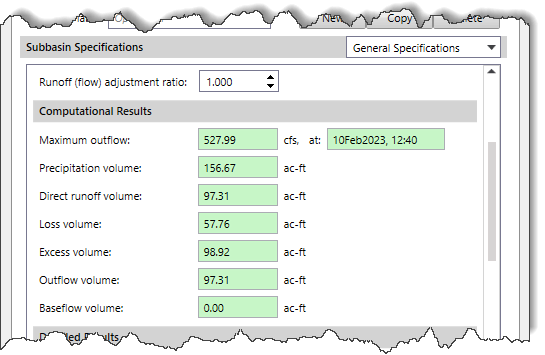
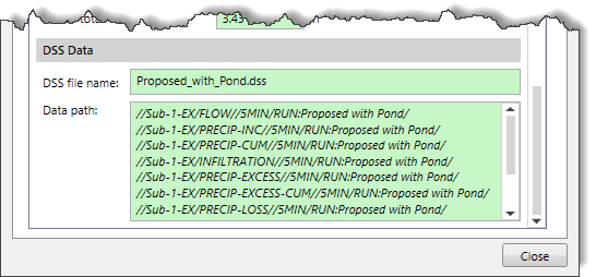
This section includes an external DSS file for referencing the HEC-HMS computational results. It allows the user to easily copy the references and paste them into GeoHECRAS.
The Baseflow Data panel is used to enter the data for the selected baseflow method for the defined subbasins. This panel is displayed when the Baseflow Data option is selected in the Subbasin Specifications dropdown combo box. Note that the Baseflow Data panel content changes based upon the baseflow method selected in the General Specifications section.
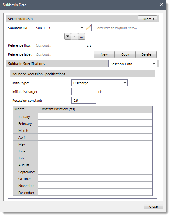
Refer to this article in our knowledge base to learn more about this panel.
The Canopy Data panel is used to enter data for the selected canopy method for the defined subbasins. This panel is displayed when the Canopy Data option is selected in the Subbasin Specifications dropdown combo box. Note that the Canopy Data panel content changes based upon the canopy method selected in the General Specifications section.
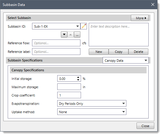
Refer to this article in our knowledge base to learn more about this panel.
The Infiltration (Loss) Data panel is used to enter data for the selected infiltration method for the defined subbasins. This panel is displayed when the Infiltration (Loss) Data option is selected in the Subbasin Specifications dropdown combo box. Note that the Infiltration (Loss) Data panel content changes based upon the infiltration (loss) method selected in the General Specifications section.
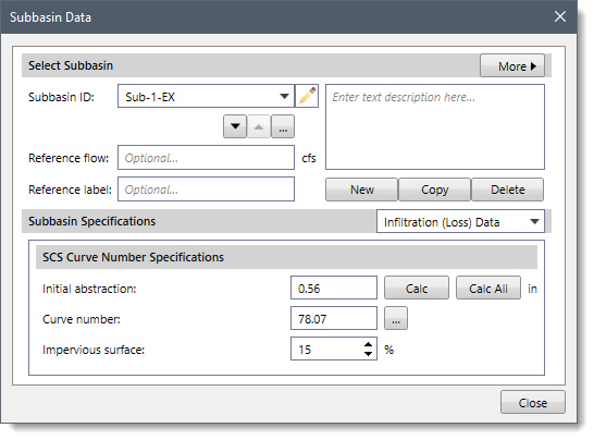
Refer to this article in our knowledge base to learn more about this panel.
The Runoff (Transform) Data panel is used to enter data for the selected runoff method for the defined subbasins. This panel is displayed when the Runoff (Transform) Data option is selected in the Subbasin Specifications dropdown combo box. Note that the Runoff (Transform) Data panel content changes based upon the runoff (transform) method selected in the General Specifications section.
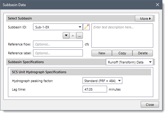
Refer to this article in our knowledge base to learn more about this panel.
The Surface Storage Data panel is used to enter data for the selected surface storage method for the defined subbasins. This panel is displayed when the Surface Storage Data option is selected in the Subbasin Specifications dropdown combo box. Note that the Surface Storage Data panel content changes based upon the surface storage method selected in the General Specifications section.
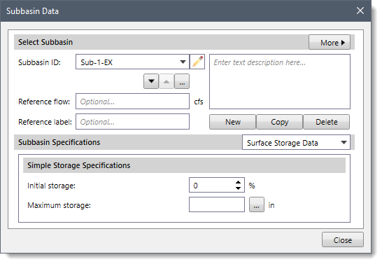
Refer to this article in our knowledge base to learn more about this panel.


CivilGEO G2 Reviews
4.8/5.0 Rating, Over 230 Reviews

GeoHECRAS is recognized as the top Civil Engineering Design Software with an average of 4.8 out of 5.0 rating from over 230 real user reviews on G2.


We use cookies to give you the best online experience. By agreeing you accept the use of cookies in accordance with our cookie policy.
When you visit any web site, it may store or retrieve information on your browser, mostly in the form of cookies. Control your personal Cookie Services here.


