Subbasins define the drainage area polygons that produce runoff to the other elements in the model. While a subbasin element conceptually represents infiltration, surface runoff, and subsurface processes interacting together, the actual subsurface calculations are performed by a baseflow method contained within the subbasin. There are many different baseflow methods provided with HEC-HMS. Some methods are designed primarily for simulating events, while others are intended for continuous simulation.
In GeoHECHMS, the baseflow method for a subbasin can be selected from the General Specifications section of the Subbasin Data dialog box. Each subbasin may use a different method, or several subbasins may use the same method.
Follow the steps below to select a baseflow method:
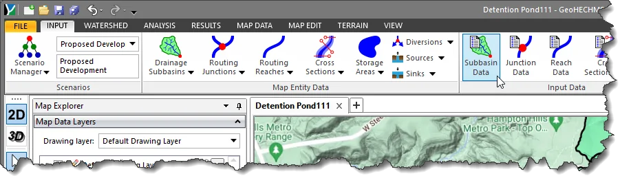
- From the Input ribbon menu, select the Subbasin Data command.
- The Subbasin Data dialog box will be displayed.
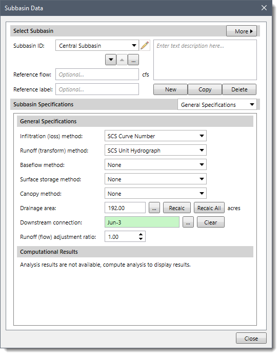
- From the Subbasin ID dropdown combo box, select the subbasin to assign a baseflow method.
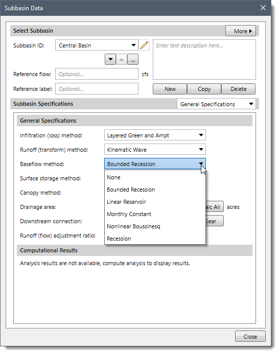
- From the Baseflow method dropdown combo box, select the baseflow method.
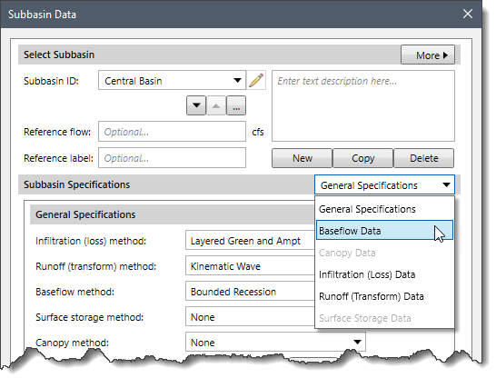
- To enter the parameters for the selected baseflow method, select the Baseflow Data option from the Subbasin Specifications dropdown combo box. Note that identical parameters between different baseflow methods are shared so that the user does not have to enter the data twice when switching between methods.
- The Baseflow Data panel will be displayed. Note that the Baseflow Data panel content changes based upon the baseflow method selected in the General Specifications section.
The following sections describe the different baseflow methods and how to enter the parameters for each method in the Baseflow Data panel.
Baseflow Method: None
When None is selected for the baseflow method, the Baseflow Data dropdown combo box entry is disabled (i.e., grayed out).
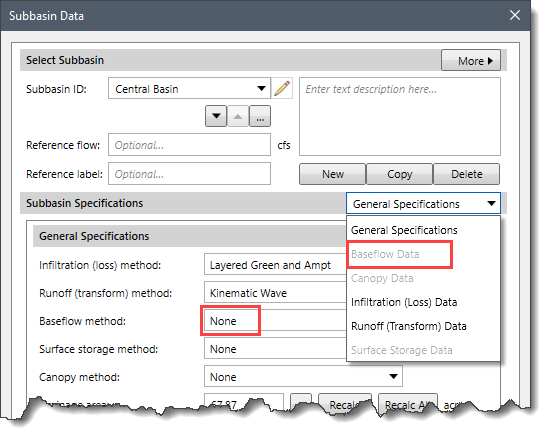
If None is selected for the baseflow method, the subbasin will not compute baseflow, and the outflow will only include direct runoff from the transform method.
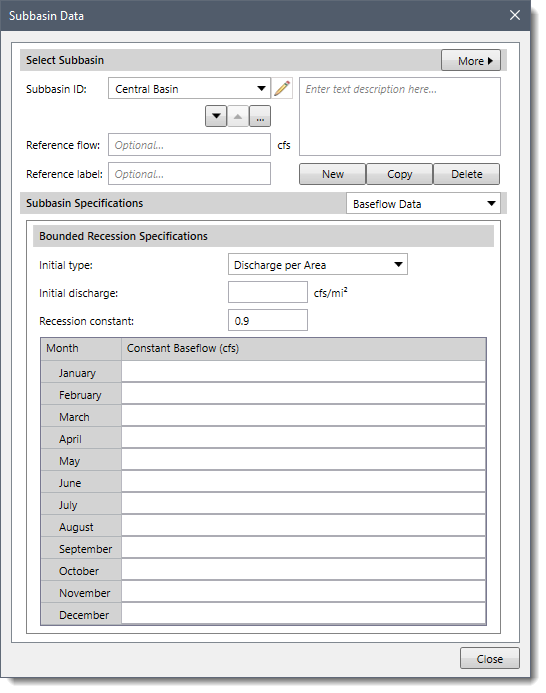
Baseflow Method: Bounded Recession
The bounded recession baseflow method is intended primarily for real-time forecasting operations. The method is very similar to the recession method (explained below) and does not conserve mass in the subbasin. The principal difference is that the bounded recession method allows for the specification of monthly baseflow limits. The baseflow is computed according to the recession methodology, and then the monthly limits are imposed. Though there are many similarities with the recession method, one important difference is that this method does not reset the baseflow after a storm event.
When Bounded Recession is selected for the baseflow method, the following data panel will be displayed:
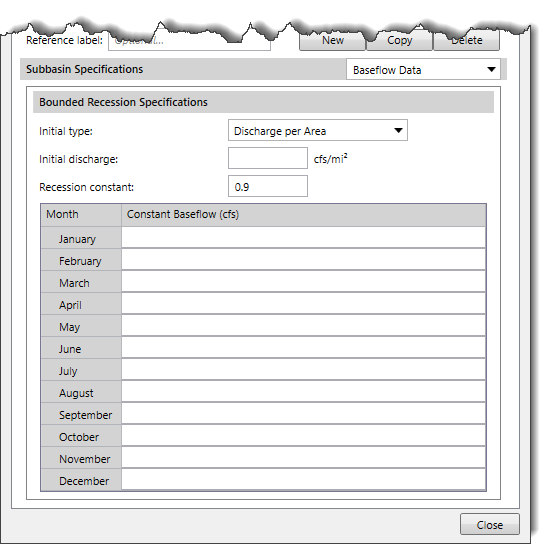
The following input parameters are provided in the data panel:
- Initial type
This dropdown combo box allows the user to select one of the following options to specify the initial baseflow at the beginning of a simulation:
- Discharge: When this option is selected, the user must specify the initial baseflow as a discharge in units of volume per time (cfs). Selecting this option is particularly effective at determining the channel’s initial flow when there is observed streamflow data at the subbasin outlet.
- Discharge per Area (default): When this option is selected, the user must specify the initial baseflow as a discharge in units of volume per area per time (cfs/mi2). Selecting this option is particularly effective when general guidelines for watershed yield must be used to estimate the initial flow.
- Initial discharge
This entry field is used to specify the amount of initial baseflow at the beginning of the simulation.
- Recession constant
This entry field specifies the rate at which baseflow recedes between storm events. It is defined as the ratio of baseflow at the current time to the baseflow one day earlier.
Furthermore, baseflow values for the months of January through December must be put in the table. These values are used to limit the computed baseflow.
Baseflow Method: Linear Reservoir
The linear reservoir baseflow method, as its name implies, uses a linear reservoir to model the recession of baseflow after a storm event. It is the only baseflow method that conserves mass within the subbasin. Infiltration or percolation computed by the infiltration method is provided as the inflow to the linear reservoirs. This method can use one, two, or three reservoirs. Partition fractions are used to split the inflow to each of the reservoirs. The inflow is multiplied by the partition fraction to determine the amount of inflow going to each reservoir. The sum of the partition fractions must be less than or equal to one. If the sum of the fractions is less than one, the remaining percolated water is considered as aquifer recharge. If the sum of the fractions is exactly equal to one, then all percolation will become baseflow, and there will be no aquifer recharge.
All losses from the SCS Curve Number, Exponential, Initial and Constant, Green and Ampt, and Smith-Parlange infiltration methods are routed to the linear reservoir baseflow model. Only percolation losses (during saturated conditions) in the Soil Moisture Accounting, Layered Green and Ampt, and Deficit and Constant infiltration methods are routed to the linear reservoir baseflow model. Refer to this article in our knowledge base to learn more about the infiltration methods.
When using the linear reservoir method with the Soil Moisture Accounting method, the number of baseflow reservoirs should be consistent with the number of groundwater layers in the infiltration method. The lateral outflow from the upper and lower groundwater layers is provided as the inflow to baseflow reservoirs 1 and 2. The percolation out of the lower groundwater layer is provided as inflow to baseflow reservoir 3. Partition fractions are not used for baseflow reservoirs 1 and 2 because their inflow is determined by the respective lateral outflow. A partition fraction should be used with the percolation to define the split between aquifer recharge and inflow to baseflow reservoir 3.
When Linear Reservoir is selected for the baseflow method, the following data panel will be displayed:
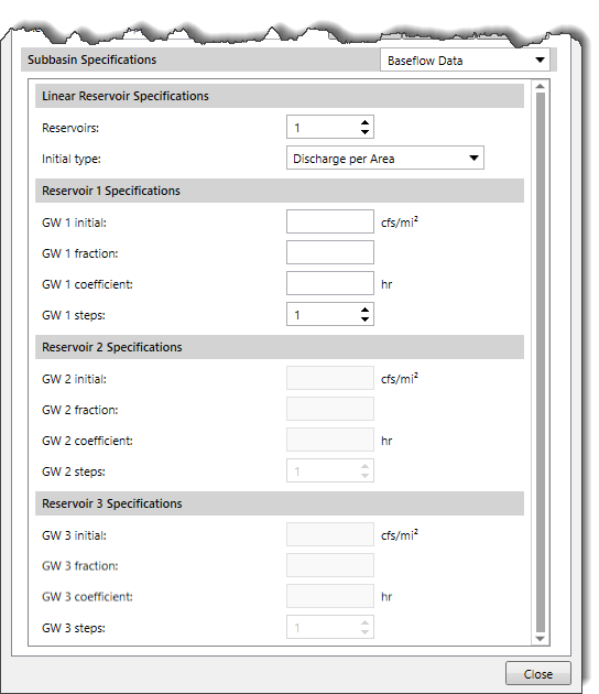
The following input parameters are provided in the data panel:
- Reservoirs
This spin control button is used to specify the number of reservoirs (number of groundwater layers). The minimum is one, and the maximum is three. Separate initial conditions and parameters must be specified for each reservoir. The Reservoir 2/3 Specifications sections are enabled or disabled based on the number of reservoirs specified.
- Initial type
This dropdown combo box allows the user to select one of the following options to specify the initial baseflow at the beginning of the simulation:
- Discharge
- Discharge per Area (default)
- GW 1/2/3 initial
These entry fields are used to specify the amount of initial baseflow for each of the reservoirs.
- GW 1/2/3 fraction
These entry fields determine how water from the infiltration method is distributed to the reservoirs. Each fraction must be greater than zero and less than or equal to one. When the sum of the fractions is one, there will be no aquifer recharge. When the sum of the fractions is less than one, the remainder of the percolation becomes aquifer recharge.
- GW 1/2/3 coefficient
These entry fields define the time constant for each reservoir (linear reservoir coefficient). Since this coefficient is measured in hours, it gives a sense of the response time for a component of subsurface flow within a subbasin.
- GW 1/2/3 steps
These spin control buttons are used to define the number of routing steps to subdivide the routing through each reservoir. The routing steps relate to the amount of attenuation during the routing. Minimum attenuation is achieved when only one routing step is defined. Baseflow attenuation increases as the number of steps increases.
Baseflow Method: Monthly Constant
The monthly constant baseflow method allows the specification of a constant baseflow for each month of the year. It does not conserve mass within the subbasin. It is intended primarily for continuous simulation in subbasins where a constant flow for each month approximates the baseflow.
When Monthly Constant is selected for the baseflow method, the following data panel will be displayed:
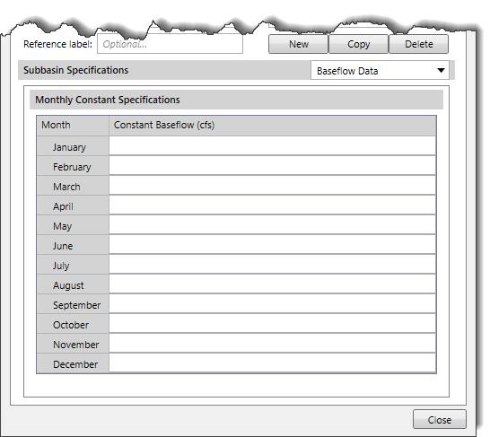
Baseflow values for January through December must be entered into the table. These values are used to limit the computed baseflow.
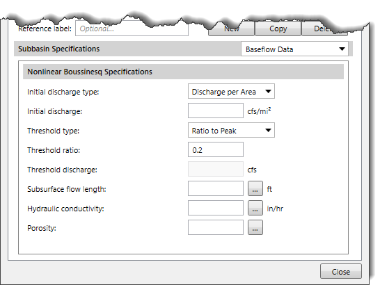
Baseflow Method: Nonlinear Boussinesq
The nonlinear Boussinesq baseflow method is designed to approximate the typical behavior observed in subbasins when channel flow recedes after an event. This method is similar to the recession baseflow method but can be parameterized using observable field data. This method is intended primarily for event simulation. However, it can also be used for continuous simulation because of its ability to reset automatically after each storm event. It does not conserve mass within the subbasin.
When Nonlinear Boussinesq is selected for the baseflow method, the following data panel will be displayed:
The following input parameters are provided in the data panel:
- Initial discharge type
This dropdown combo box allows the user to select one of the following options to specify the initial baseflow at the beginning of the simulation.
- Discharge
- Discharge per Area (default)
- Initial discharge
This entry field is used to specify the amount of initial baseflow at the beginning of the simulation.
- Threshold type
This dropdown combo box allows the user to select one of the following options to reset the baseflow during a storm event:
- Ratio to Peak (default)
- Threshold Discharge
- Threshold ratio
This entry is only enabled if the Ratio to Peak option is selected for the Threshold type. Otherwise, this entry is disabled (i.e., grayed out). It specifies the flow ratio to the peak. The baseflow is reset when the current flow divided by the peak flow falls to the specified value. For example, if a ratio of 0.2 is provided, the baseflow will reset on the receding limb of an event hydrograph when the flow has decreased to 20% of the event peak flow.
- Threshold discharge
This entry field is only enabled if the Threshold discharge is selected for the Threshold type. Otherwise, this entry is disabled (i.e., grayed out). It specifies the threshold baseflow value. The baseflow is always reset when the receding limb of the hydrograph falls to the specified flow value, regardless of the peak flow during the previous storm event.
- Subsurface flow length
This entry field is used to specify the characteristic subsurface flow length. This could be estimated as the mean distance from the subbasin boundary to the stream. Clicking the […] button allows the user to measure the subsurface flow length from the Map View.
- Hydraulic conductivity
This entry field is used to specify the conductivity of the soil. This could be estimated from field tests or from the soil texture. Clicking the […] lookup button will display the Soil Saturated Hydraulic Conductivity lookup dialog box.
- Porosity
This entry field is used to specify the drainable porosity in terms of volume ratio. The upper limit would be the total porosity minus the residual porosity. The actual drainable porosity depends on local conditions.
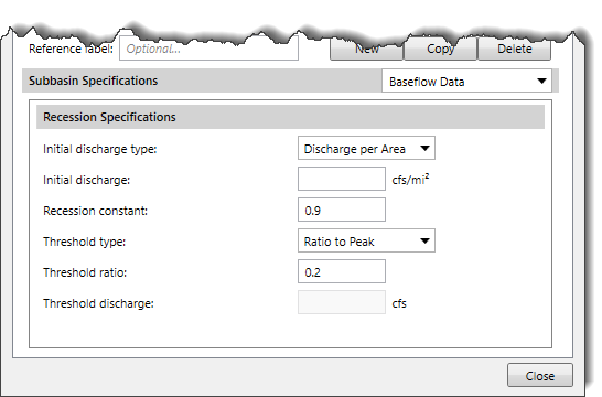
Baseflow Method: Recession
The recession baseflow method is designed to approximate the typical behavior observed in subbasins when channel flow recedes exponentially after an event. This method is intended primarily for event simulation. However, it does have the ability to automatically reset after each storm event and consequently may be used for continuous simulation. It does not conserve mass within the subbasin.
When Recession is selected for the baseflow method, the following data panel will be displayed:
The following input parameters are provided in the data panel:
- Initial type
This dropdown combo box allows the user to select one of the following options to specify the initial baseflow flow at the beginning of a simulation.
- Discharge
- Discharge per Area(default)
- Initial discharge
This entry field specifies the amount of initial baseflow at the beginning of a simulation.
- Recession constant
This entry field describes the rate at which baseflow recedes between storm events. It is defined as the ratio of baseflow at the current time, to the baseflow one day earlier.
- Threshold type
This dropdown combo box allows the user to select from one of the following options to reset the baseflow during a storm event.
- Ratio to Peak (default)
- Threshold Discharge
- Threshold ratio
This entry is only enabled if the Ratio to Peak option is selected for the Threshold type. Otherwise, this entry is disabled (i.e., grayed out). It specifies the flow ratio to the peak.
- Threshold discharge
This entry field is only enabled if the Threshold Discharge is selected for the Threshold type. Otherwise, this entry is disabled (i.e., grayed out). It specifies the threshold baseflow value. The baseflow is always reset when the receding limb of the hydrograph falls to a specified flow value, regardless of the peak flow during the previous storm event.
Pros and Cons of Baseflow Methods
| Method | Pros | Cons |
| Bounded Recession | Monthly baseflow limit can be specified using this method. | This method does not conserve mass.
The method does not reset baseflow after a storm event. |
| Monthly Constant | It is most suitable for simulation of long period data. | It does not conserve mass within the subbasin.
It is suitable only for continuous simulation. |
| Linear Reservoir | It is the only baseflow method that conserves mass within the subbasin.
This method is best suited when general guidelines for the watershed yield must be used to estimate initial flow. | It does not conserve mass within the subbasin.
It can model both interflow and groundwater flow (because it includes up to three layers, each layer has its own coefficient). |
| Nonlinear Boussinesq | Provides a response similar to the recession method. However, the parameters can be estimated from measurable qualities of the watershed. | It does not conserve mass within the subbasin. |
| Recession | The method has ability to reset after each storm event and consequently can be used for continuous simulation. | The method does not conserve mass.
It cannot model both interflow and groundwater flow (there is only one recession constant). |


