Storage areas define the elements (i.e., reservoirs, lakes, detention ponds, storage nodes, etc.) where there are one or more inflows and only one computed outflow. Inflow comes from other elements in the model, such as drainage basins, routing reaches, or diversions. If there is more than one inflow, all inflow is added together before computing the outflow. It is assumed that the water surface in the storage area pool is level.
In GeoHECHMS, the Storage Area Data command allows the user to define different computational methods and options for each storage area of the model.
Follow the steps below to define the storage area data using the Storage Area Data command:
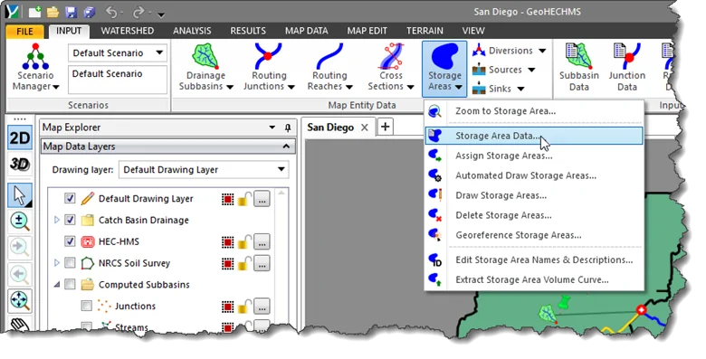
- From the Input ribbon menu, select the Storage Area Data command.
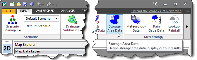
Alternatively, select the Storage Area Data command under the Storage Areas dropdown menu.
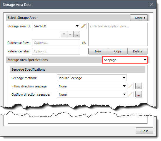
- The Storage Area Data dialog box will be displayed.
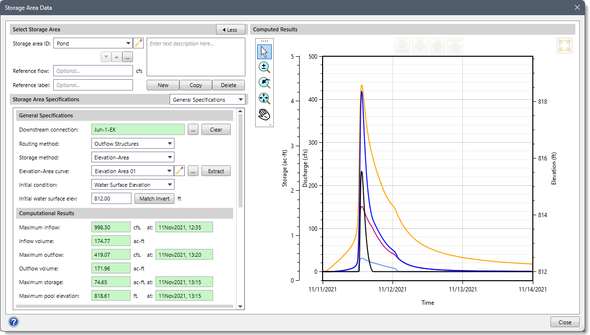
The following sections describe how to define the storage area data and interact with the above dialog box.
Selecting Storage Area
The Select Storage Area section allows the user to select a storage area for defining the storage area data.
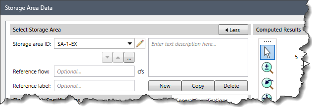
This section contains the following options:
- Storage area ID
This dropdown entry displays the ID of the selected storage area, which is also editable. The up and down arrow buttons allow the user to navigate between the next or previous storage area. The […] button allows the user to select a storage area from the Map View.
- Reference flow
This optional entry field allows the user to assign a reference flow to the selected storage area.
- Reference label
This optional entry field allows the user to assign a reference label to the selected storage area.
- New
The [New] button allows the user to draw a new storage area on the Map View.
- Copy
The [Copy] button allows the user to create a copy of the current storage area on the Map View.
- Delete
The [Delete] button allows the user to delete the current storage area.
- Description
This optional entry field allows the user to include information on the current storage area.
- Less/More
The [< Less] and [More >] buttons at the Select Storage Area section header allow the user to hide and display the right side of the dialog box containing the Computed Results plot. This allows the dialog box to be smaller when the user does not want to see the plot view.
Once the user selects the required storage area, the following panels from the Storage Area Specifications dropdown entry can be used to view and edit the associated storage area data.
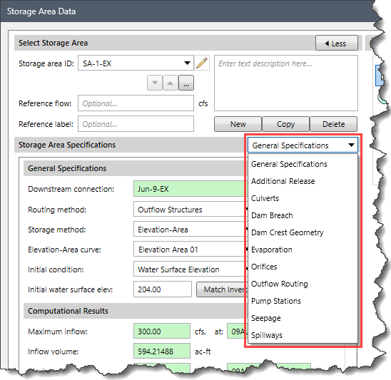
Storage Area Specifications
This section contains a dropdown combo box with the following data panel entries, each of which allows the user to define relevant storage area data:
- General Specifications
- Additional Release
- Culverts
- Dam Breach
- Dam Crest Geometry
- Evaporation
- Orifices
- Outflow Routing
- Pump Stations
- Seepage
- Spillways
General Specifications
This data panel allows the user to define the general properties of the current storage area.
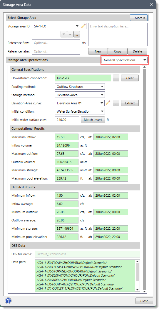
The General Specifications section of this data panel contains the following options:
- Downstream connection
This optional entry field defines the downstream connection element that the selected storage area drains to such as Diversion, Junction, Reach, Storage Area, and Sink. Clicking the […] pick button allows the user to select the downstream connection element from the Map View.
- Routing method
The routing methods under this dropdown combo box are used to compute the flow through the storage area. This dropdown combo box provides the following entries:
- None
- Outflow Curve (default)
- Outflow Structures
- Specified Release
- Storage method
The storage methods under this dropdown combo box are used to define the storage area relationship. The routing through a reservoir, lake, detention pond, or storage node assumes that the water surface in the storage area is level. This dropdown combo box provides the following storage methods based upon the selected routing method:
| Routing Method | Storage Method |
| None | Storage method entry will be disabled |
| Outflow Curve | - Elevation-Area-Discharge (default)
- Elevation-Storage-Discharge
- Storage-Discharge
|
| Outflow Structures | - Elevation-Area (default)
- Elevation-Volume
|
| Specified Release | - Elevation-Area (default)
- Elevation-Volume
|
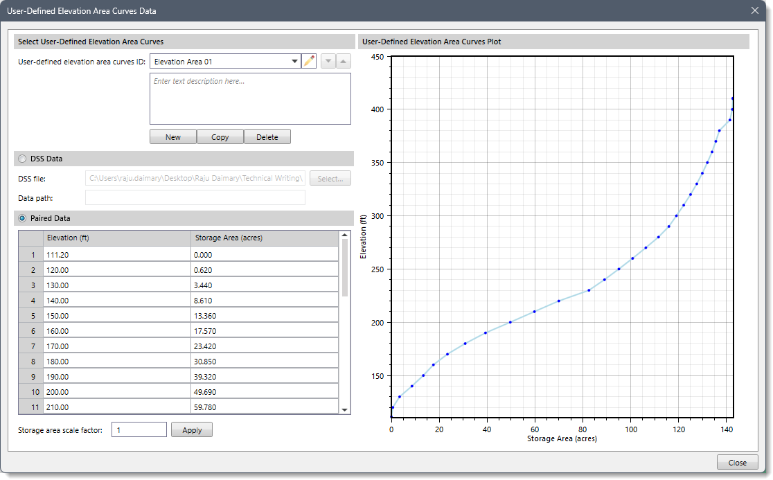
- Elevation-Area curve
This dropdown combo box is only available if Elevation-Area-Discharge or Elevation-Area is selected as the storage method. This dropdown combo box allows the user to select an already-defined elevation area curve. Clicking the adjacent […] button displays a User-Defined Elevation Area Curves Data paired data dialog box that allows the user to define a new user-defined elevation area curve.
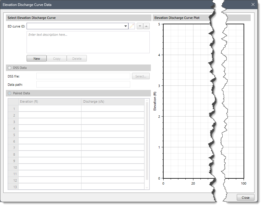
- Elevation-Discharge curve
This dropdown combo box is only available if Elevation-Area-Discharge is selected as the storage method. This dropdown combo box allows the user to select an already-defined elevation discharge curve. Clicking the adjacent […] button displays an Elevation Discharge Curve Data paired data dialog box that allows the user to define a new user-defined elevation discharge curve.
- Storage-Discharge curve
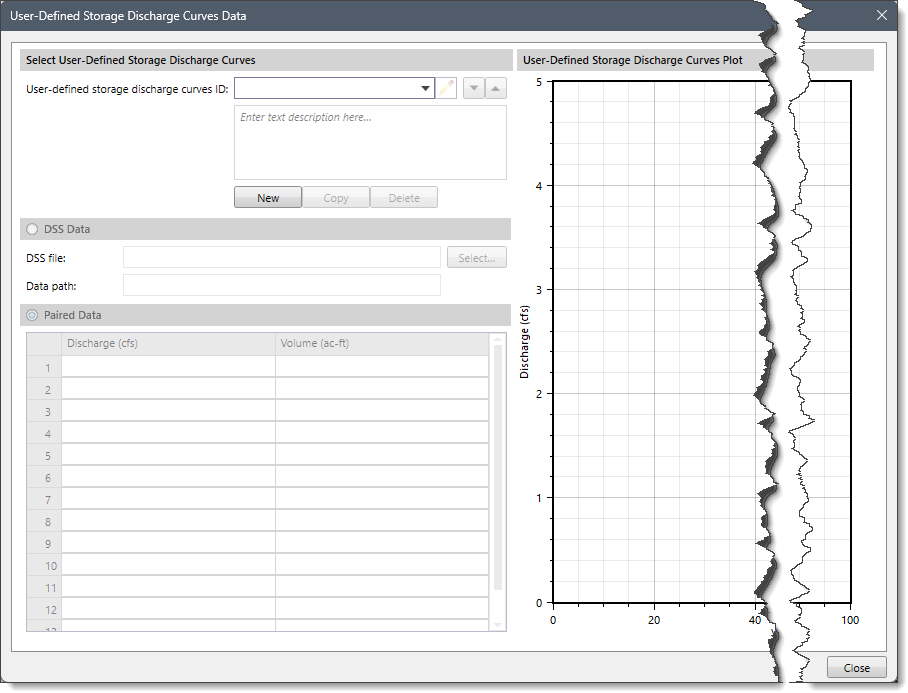
This dropdown combo box is only available if Elevation-Storage-Discharge or Storage-Discharge is selected as the storage method. This dropdown combo box allows the user to select an already-defined storage discharge curve. Clicking the adjacent […] button displays a User-Defined Storage Discharge Curves Data paired data dialog box that allows the user to define a new user-defined storage discharge curve.
- Primary data curve
This dropdown combo box entry defines which user-defined paired data curve should be considered the primary table for interpolating values. This dropdown combo box is only visible if Elevation-Area-Discharge or Elevation-Storage-Discharge is selected as the storage method. This dropdown combo box provides the following entries based upon the selected storage method:
| Storage Method | Primary Data Curve |
| Elevation-Area-Discharge | - Elevation-Area
- Elevation-Discharge (default)
|
| Elevation-Storage-Discharge | - Elevation-Storage
- Storage-Discharge (default)
|
- Initial condition
This dropdown combo box entry sets the amount of stored water in the storage area at the start of the simulation. Various routing methods are provided for computing the flow through the storage area. This dropdown combo box provides the following entries based upon the selected routing and storage method:
| Storage Method & Routing Method | Initial Condition |
Routing Method = Outflow Curve
Storage Method = Elevation-Area-Discharge | - Discharge
- Water Surface Elevation
- Inflow = Outflow (default)
|
Routing Method = Outflow Curve
Storage Method = Elevation-Storage-Discharge | - Discharge (default)
- Water Surface Elevation
- Inflow = Outflow
- Storage
|
Routing Method = Outflow Curve
Storage Method = Storage-Discharge | - Discharge
- Inflow = Outflow (default)
- Storage
|
Routing Method = Outflow Structures
Storage Method = Elevation-Area | - Water Surface Elevation
- Inflow = Outflow (default)
|
Routing Method = Specified Release
Storage Method = Elevation-Area | - Water Surface Elevation (default)
|
Routing Method = Outflow Structures
Storage Method = Elevation-Storage | - Water Surface Elevation
- Inflow = Outflow (default)
- Storage
|
Routing Method = Specified Release
Storage Method = Elevation-Storage | - Water Surface Elevation (default)
- Storage
|
- Initial water surface elevation
This entry defines the initial water surface elevation contained within the storage area. This entry is only available when the Initial Condition entry has been set to the Water Surface Elevation.
- Initial discharge
This entry defines the initial discharge being released from the storage area. This entry is only available when the Initial Condition entry has been set to the Discharge.
- Initial storage
This entry defines the initial storage contained within the storage area. This entry is only available when the Initial Condition entry has been set to Storage.
- Discharge time series gage
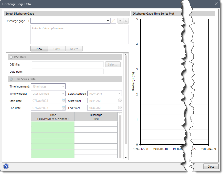
This dropdown combo box is only available when the Routing Method entry has been set to Specified Release. This dropdown combo box allows the user to select an already defined discharge gage. Clicking the adjacent […] button will display a Discharge Gage Data time series data dialog box that allows the user to define a new user-defined discharge gage.
- Maximum discharge warning
This entry is only available when the Routing Method entry has been set to Specified Release. This optional entry specifies whether a warning message should be displayed when the computed storage area discharge exceeds the specified maximum discharge value. If the computed discharge exceeds this value during a simulation, then a warning message will be displayed. However, this entry will not affect the discharge released from the storage area.
- Maximum capacity warning
This entry is only available when the Routing Method entry has been set to Specified Release. This optional entry specifies whether a warning message should be displayed when the computed storage exceeds the specified maximum capacity value. If the computed storage exceeds this value during a simulation, then a warning message will be displayed. However, this entry will not affect the computed storage contained in the storage area.
Computational and Detailed Results
The Computational Results and Detailed Results sections contain the following storage area results obtained after running the project’s analysis:
- Maximum and minimum inflow
- Maximum and minimum outflow
- Maximum and minimum storage
- Maximum and minimum pool elevation, etc
DSS Data
This section includes an external DSS (Digital Storage System) file for referencing the HEC-HMS computational results. The DSS file name field displays the external DSS file to be used for reading the data. The Data path field displays the data path within the DSS file for the data to be read from.
Additional Release
This data panel is enabled when Outflow Structures is selected as the routing method. Otherwise, this data panel entry is disabled (i.e., grayed out).
In most situations, a dam can be properly configured using the provided outlet structures, such as spillways, outlets, etc. The total outflow from the storage area can be calculated automatically using the physical properties defined for each of the included structures. However, some storage areas may have an additional release beyond what is represented by the defined structures.
In some cases, this additional release is a schedule of managed releases achieved by operating the spillway gates. The additional release can be used in combination with other outlet structures to determine the total release from the storage area.
This data panel contains the following section:
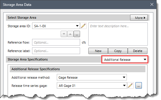
Additional Release Specifications
This section contains the following options:
- Additional release method
This dropdown combo box entry defines how the additional release is computed at the storage area. This dropdown combo box provides the following entries:
- None (default)
- Gage Release
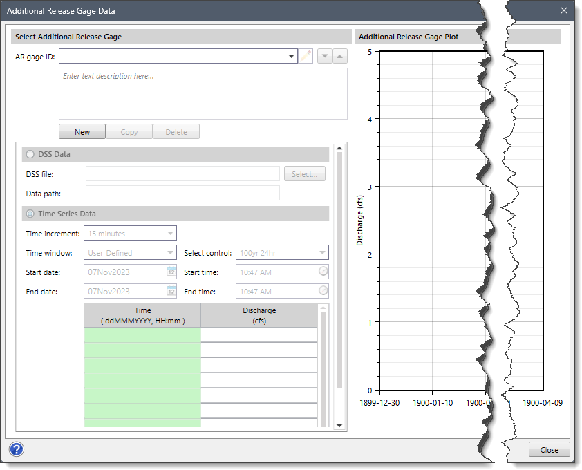
- Release time series gage
This dropdown combo box is enabled if the Gage Release is selected as the additional release method. This dropdown combo box allows the user to select an already defined discharge gage. Clicking the […] button displays an Additional Release Gage Data time series data dialog box that allows the user to define a new user-defined discharge gage.
Culverts
This data panel is enabled when Outflow Structures is selected as the routing method. Otherwise, this data panel entry is disabled (i.e., grayed out).
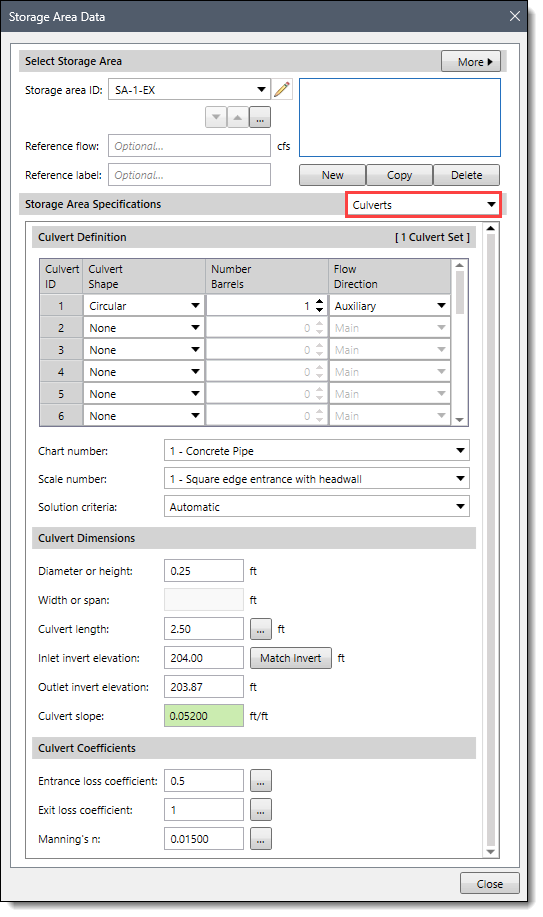
Refer to this article to learn more about the Culverts data panel of the Storage Area Data dialog box.
Dam Breach
This data panel is enabled when Outflow Structures is selected as the routing method. Otherwise, this data panel entry is disabled (i.e., grayed out).
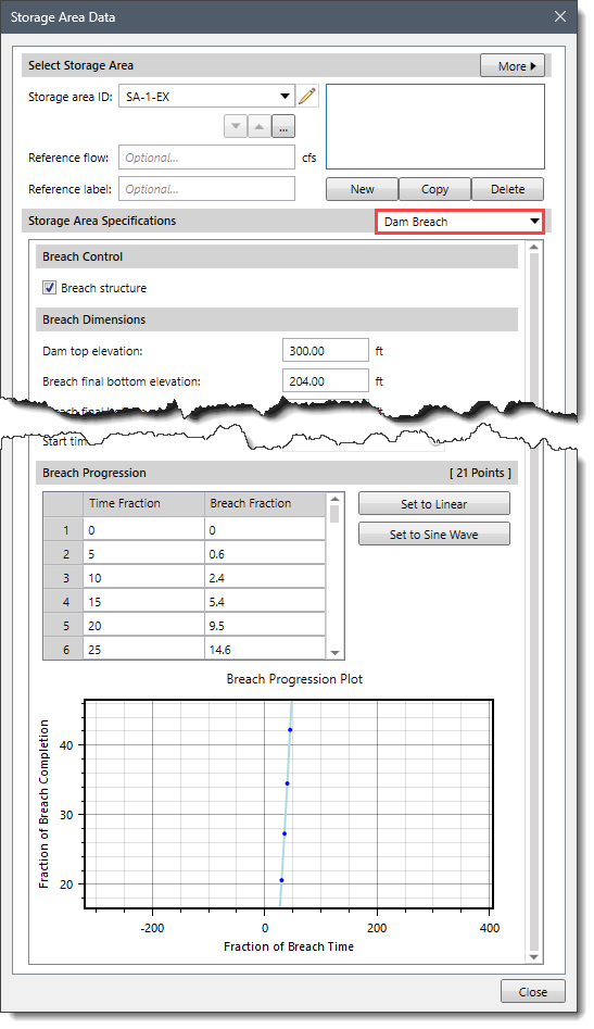
Refer to this article to learn more about the Dam Breach data panel of the Storage Area Data dialog box.
Dam Crest Geometry
This data panel will be enabled when Outflow Structures is selected as the routing method. Otherwise, this data panel entry is disabled (i.e., grayed out).
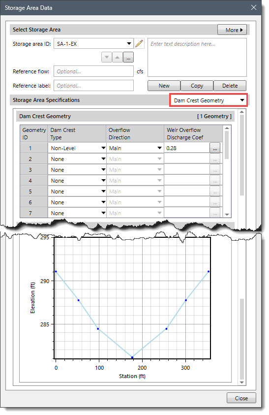
Refer to this article to learn more about the Dam Crest Geometry data panel of the Storage Area Data dialog box.
Evaporation
This data panel will only be enabled when the following conditions are met:
- Outflow Structures is selected as the routing method.
- Elevation-Area is selected as the storage method.
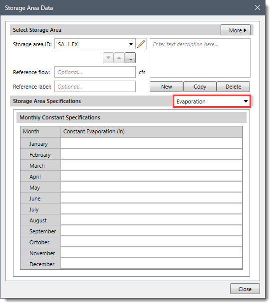
Water losses due to evaporation may be an important part of the water balance for a storage area, especially in dry or desert conditions. The evaporation losses are different from other structures because they do not contribute to either main or auxiliary outflows downstream. The evaporation losses are computed separately and are available for review with the other time-series results for the storage area. An evaporation depth is computed for each time interval and then multiplied by the current surface area. In the Monthly Constant Specifications data table, the monthly Constant Evaporation value is used to represent the water loss, entered as a total depth for the month.
Orifices
This data panel will be enabled when Outflow Structures is selected as the routing method. Otherwise, this data panel entry is disabled (i.e., grayed out).
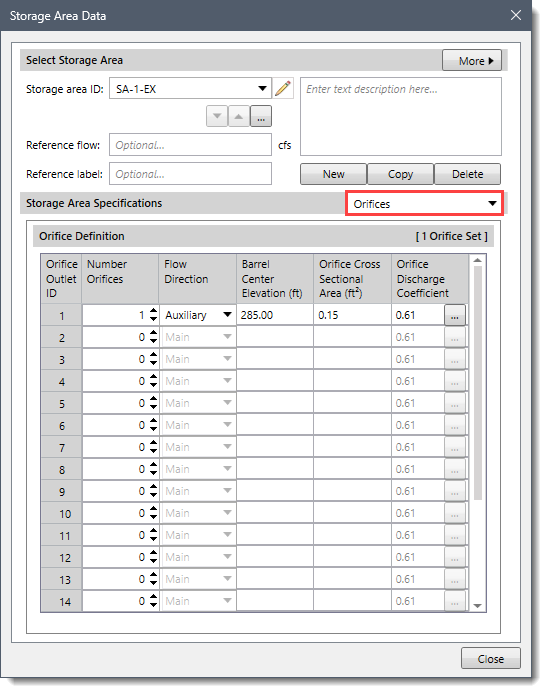
This data panel contains the following sections:
Orifice Definition
The data table under this section contains the following parameters:
- Number Orifices
This spin control field defines the number of identical orifice barrels that are defined.
- Flow Direction
This dropdown combo box entry defines where the orifice flow is being routed. The following dropdown entries are available:
- Main (default)
- Auxiliary
- Barrel Center Elevation
This entry defines the center of the cross-sectional flow area. This should be measured in the same vertical datum as the paired data functions defining the storage characteristics of the reservoir. It is used to compute the pressure head on the outlet, so no flow will be released until the storage area pool elevation is above this specified elevation.
- Orifice Cross Sectional Area
This entry defines the cross-sectional flow area of the orifice. The orifice assumptions are independent of the orifice shape.
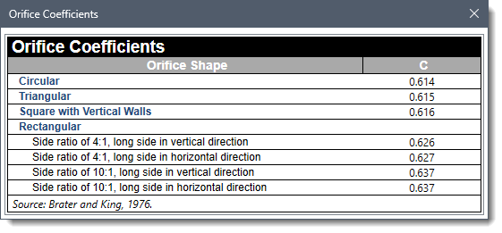
- Orifice Discharge Coefficient
This entry defines the dimensionless discharge coefficient of the orifice. This coefficient describes the energy loss as water exits the storage area through the outlet. Clicking the […] button displays the Orifices Coefficients lookup dialog box.
Outflow Routing
This data panel will be enabled when Outflow Structures is selected as the routing method. Otherwise, this data panel entry is disabled (i.e., grayed out).
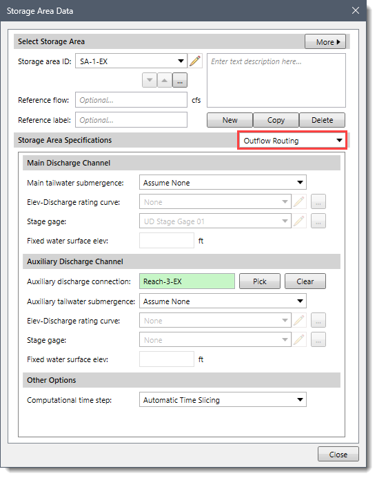
Refer to this article to learn more about the Outflow Routing data panel of the Storage Area Data dialog box.
Pump Stations
This data panel will be enabled when Outflow Structures is selected as the routing method. Otherwise, this data panel entry is disabled (i.e., grayed out). Pumping from a storage area is meant to represent low-head, high-flow situations. The pump should be designed for high flow rates against a relatively small head. The pump can be controlled to turn on and off as the storage area pool elevation changes.
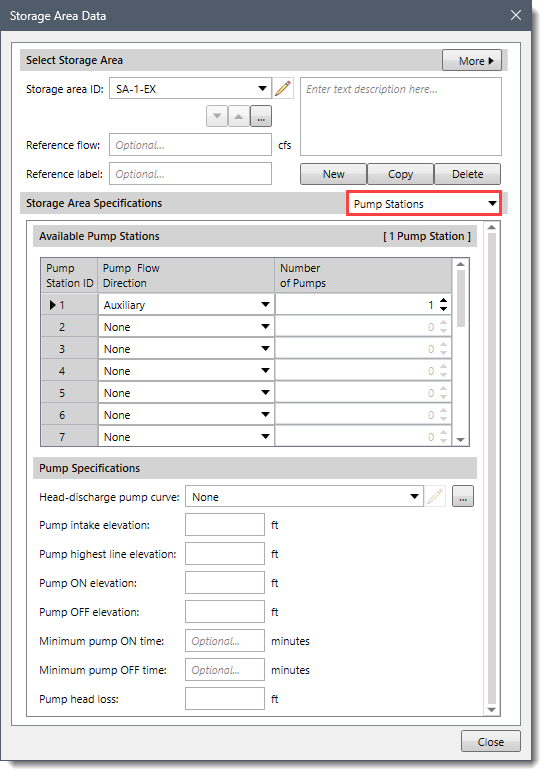
This data panel contains the following sections:
Available Pump Stations
The Pump Flow Direction dropdown combo box of the data table allows the user to define where the pump flow is being routed. This dropdown combo box provides the following entries:
- None (default)
- Main
- Auxiliary
The Number of Pumps spin control defines the number of identical pumps in operation at the diversion. This allows pump data to be defined only once when there are multiple pump units of the same type being used throughout the model.
Pump Specifications
This section contains the following options:
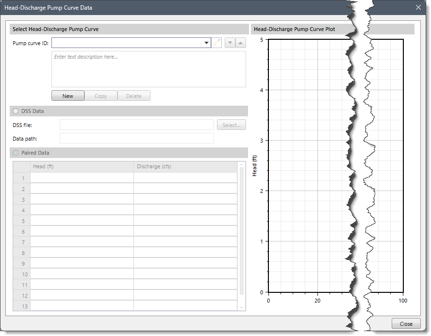
- Head-discharge pump curve
The head-discharge curve defines the pumping capacity of the pump as a function of the total head. This dropdown combo box allows the user to select an already-defined pump curve. Clicking the […] button displays the Head-Discharge Pump Curve Data paired data dialog box that allows the user to define a new user-defined pump curve.
- Pump intake elevation
This entry defines the elevation for the pump intake.
- Pump highest line elevation
This entry defines the highest elevation in the pump pressure line from the pump to the discharge point.
- Pump ON elevation
This entry defines the trigger elevation for the pump to turn on. Once the pump turns on, it will remain on until the stage in the intake drops below this trigger elevation.
- Pump OFF elevation
This entry defines the trigger elevation for the pump to turn off. Once the pump turns off, it will remain off until the stage in the intake exceeds the “pump on” elevation. This elevation must be below the “pump on” elevation.
- Minimum pump ON time
This optional entry, if used, defines that once a pump turns on, it must remain on for the specified minimum run time—even if the intake water surface elevation drops below the trigger elevation to turn the pump off. The only exception is if the water surface elevation drops below the intake elevation and the pump starves for water. In this situation, the pump will shut off.
- Minimum pump OFF time
This optional entry, if used, directs that once a pump turns off, it must remain off for the specified minimum rest time—even if the intake water surface elevation exceeds the trigger elevation to turn the pump on.
- Pump head loss
This entry defines the energy head loss of the pump and associated equipment. This includes all energy losses between the intake and discharge points. These losses are sometimes called static losses because they do not change very much even as the water surface elevation at the intake fluctuates. Components of this loss include the following:
- Entrance losses at the intake
- Losses in the pump
- Pipe friction losses
- Pipe bend losses
- Exit losses at the discharge
Seepage
This data panel will be enabled when Outflow Structures is selected as the routing method. Otherwise, this data panel entry is disabled (i.e., grayed out).
Most dams have some water seeping through the face of the dam. The amount of seepage depends on the elevation of water in the dam, the elevation of water in the tailwater, the dam’s integrity, and other factors. In some situations, seepage from the pool through the dam and into the downstream routing reach can be a significant source of discharge that must be considered in the model (i.e., sink). In other conditions, water might seep into the storage area from external groundwater infiltration (i.e., source).
There can only be one dam seepage condition at a storage area, and it must represent the sum of all sources and sinks of seepage. When water seeps out of the storage area, the seepage is automatically taken from the storage and added to the main tailwater discharge location. This is the mode of seepage when the pool elevation is greater than the tailwater elevation. Seepage into the storage area happens when the tailwater elevation is higher than the pool elevation. In this mode, the appropriate amount of seepage is added to storage, but it is not subtracted from the tailwater.
Water losses due to evaporation may be an important part of the water balance for a storage area, especially in dry or desert conditions. The evaporation losses are different from other structures because they do not contribute to either main or auxiliary outflow downstream. The evaporation losses are accounted for separately and available for review with the other time-series results for the storage area. An evaporation depth is computed for each time interval and then multiplied by the current surface area.
This data panel contains the following sections:
Seepage Specifications
This section contains the following options:
- Seepage method
This dropdown combo box entry defines how seepage is computed at the storage area. This dropdown combo box provides the following entries:
- None (default)
- Tabular Seepage
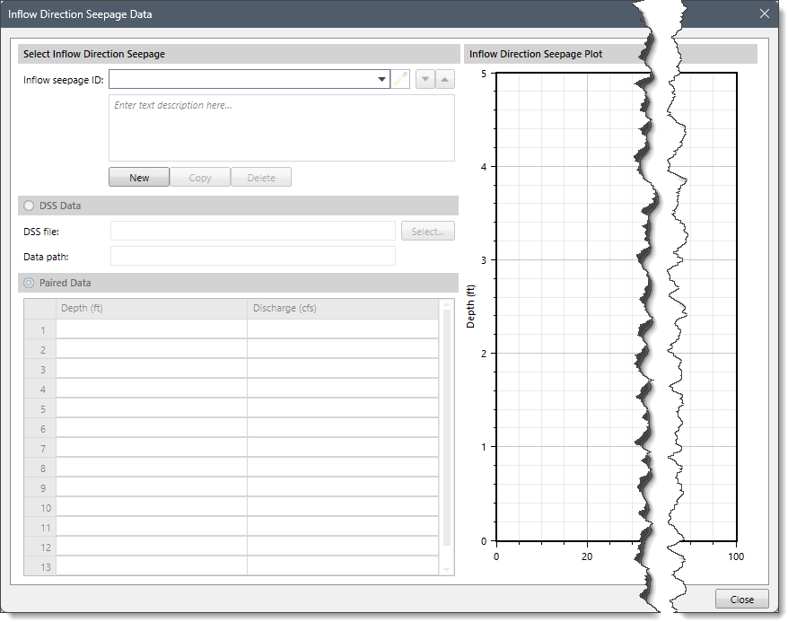
- Inflow direction seepage
This dropdown combo box will be enabled if Tabular Seepage is selected as the seepage method. This entry represents the elevation discharge rating curve to be used for modeling seepage into the storage area. No seepage out of the storage area will be represented by this entry. If desired, the same elevation discharge rating curve can be used to represent the inflow seepage and outflow seepage. Clicking the […] button displays an Inflow Direction Seepage Data paired data dialog box that allows the user to define a new elevation discharge curve.
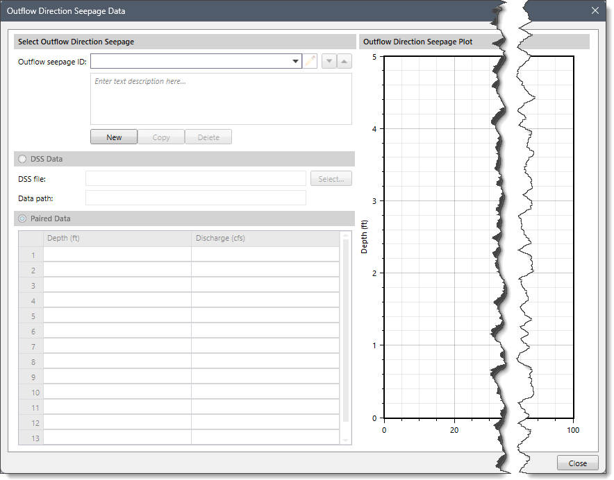
- Outflow direction seepage
This dropdown combo box will be enabled if Tabular Seepage is selected as the seepage method. This entry represents the elevation discharge rating curve to be used for modeling seepage out of the storage area. No seepage into the storage area will be represented by this entry. If desired, the same elevation discharge rating curve can be used to represent the inflow seepage and outflow seepage. Clicking the […] button displays an Outflow Direction Seepage Data paired data dialog box that allows the user to define a new elevation discharge curve.
Spillways
This data panel will be enabled when Outflow Structures is selected as the routing method. Otherwise, this data panel entry is disabled (i.e., grayed out).
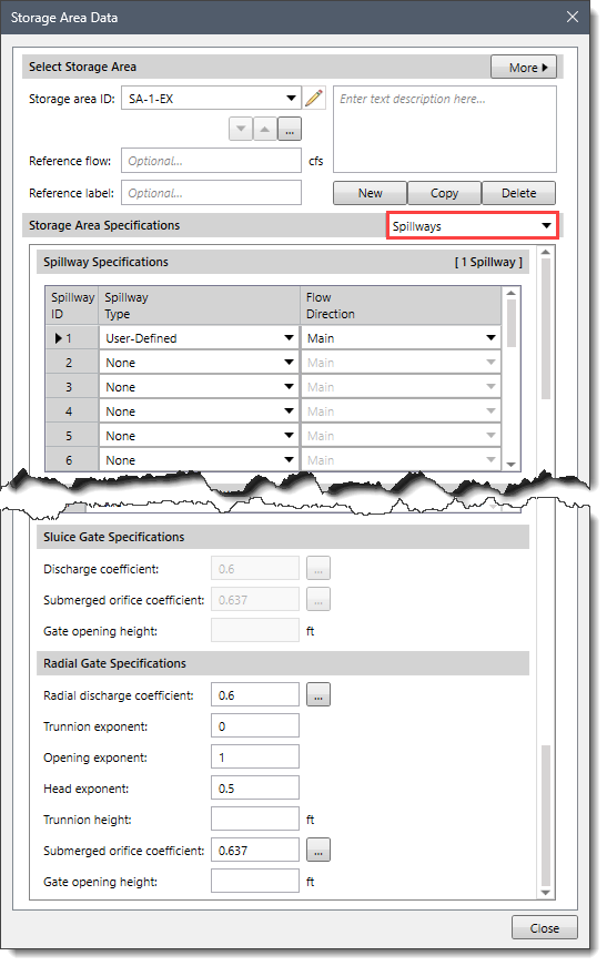
Refer to this article to learn more about the Spillways data panel of the Storage Area Data dialog box.


