
Welcome to CivilGEO Knowledge Base
Welcome to CivilGEO Knowledge Base
GeoHECHMS provides the ability to work with multiple scenarios (or plans) within a single project. Each scenario associates a specific basin model, meteorological model, and set of control specifications with a specific condition or circumstance, such as pre-developed and post-developed phases of a project.
A HEC‑HMS project is comprised of one or more scenarios (plans). Scenarios are formulated by selecting particular basin data, meteorological data, and control specifications.
The Input ribbon menu shows the currently selected scenario and a description of the scenario.
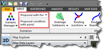
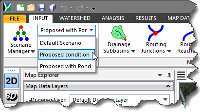
The ribbon menu dropdown combo box allows the user to quickly switch between scenarios. Moving from one scenario to another will cause the contents of the Map View to change to represent the geometry of the selected scenario.
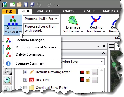
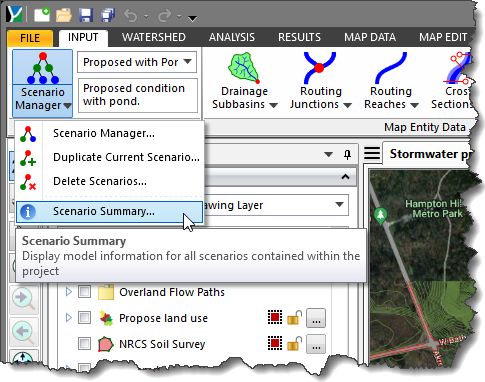
From the Input ribbon menu, expand the Scenario Manager dropdown combo box. It will display four commands: Scenario Manager, Duplicate Current Scenario, Delete Scenarios, and Scenario Summary.
Selecting the Scenario Manager command will display the below dialog box. This dialog box displays the details of the currently selected scenario in the project.
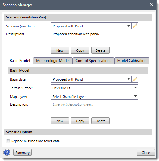
Each of these sections contains individual elements that are used to define the corresponding section data. The Scenario Manager dialog box is used to manage the basin data, meteorological data, and control specifications (i.e., basin, meteorological, and control files) associated with the current scenario. In addition, a new scenario, basin model, meteorological model, and control specification can be created, as well as copied from the existing one.
The Scenario (Simulation Run) section allows you to create new scenarios as well as manage existing scenarios. The Scenario (run data) dropdown combo box lists all the scenarios in the project. The user can select the preferred scenario to view or modify its related data. The remaining sections of the dialog box will be updated based on the user’s selection.
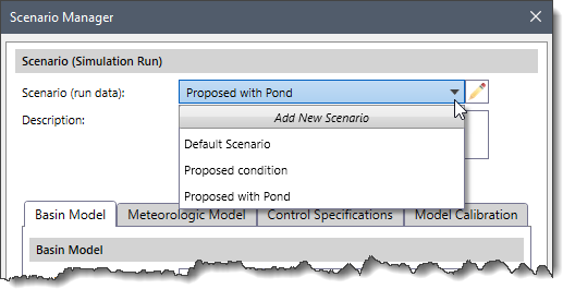
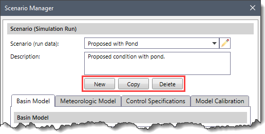
To create a new scenario, the user can select the Add New Scenario option from the Scenario (run data) dropdown combo box. Alternatively, the user can click the [New] button under the Scenario (Simulation Run) section. The default settings will be applied to the remaining sections of the Scenario Manager dialog box. The user can then specify the details for the basin model, meteorologic model, control specifications, model calibration, and other scenario options in their respective sections.
The user can click the [Copy] button to copy the current scenario plan to be further used in another scenario plan. The [Delete] button can be used to delete the currently selected scenario plan.
The Basin Model panel defines the network element data (i.e., subbasins, reaches, junctions, etc.) that define the physical model.
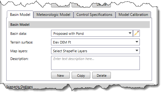
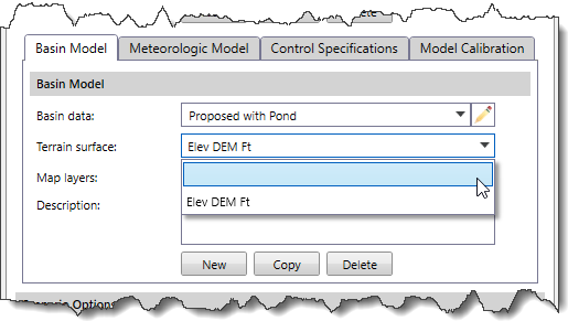
The Basin data dropdown combo box lists all the existing basin models in the current project. Similarly, the Terrain surface and Map layers dropdown combo boxes list the existing terrain surfaces in the project and the corresponding map layers related to the selected terrain surface.
Note that the user can select the blank entry from the Terrain surface dropdown combo box to dissociate a terrain from the project.
Any descriptive information about the basin model can be included in the Description text box area.
The user can select from the already existing basin models to apply to the scenario plan or click the [New] button to define a new basin model. The user can also copy the details of existing basin models by clicking the [Copy] button and later using this information in another basin model. To delete the selected basin model, the user can click the [Delete] button.
The Meteorologic Model panel defines the meteorological data (i.e., rainfall, distribution, etc.) that defines the boundary conditions applied to the model.
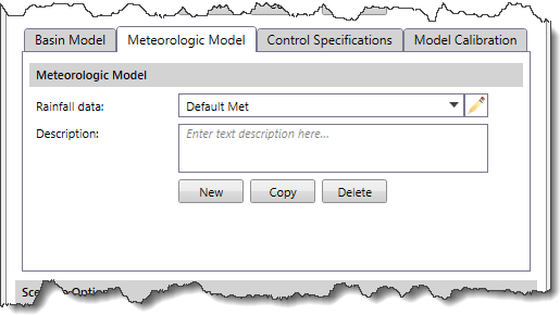
The Rainfall data dropdown combo box lists all the existing meteorological models in the current project. Any descriptive information about the meteorological model can be included in the Description text box area.
The user can define a new meteorological model, copy the details of an existing meteorological model to use in another meteorological model, and delete the selected meteorological model using the [New], [Copy], and [Delete] buttons, respectively.
The Control Specifications panel defines the control specifications (i.e., start and stop times, time steps, etc.) that are used in running the stormwater analysis for the defined model.
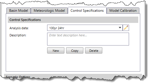
The Analysis data dropdown combo box lists all the existing control specifications in the current project. Any descriptive information about the control specification can be included in the Description text box area.
The user can define a new control specification, copy the details of an existing control specification to use in another control specification, and delete the selected control specification using the [New], [Copy], and [Delete] buttons, respectively.
The following panel is used to define the model calibration data.
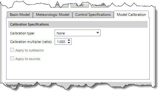
This section describes the calibration data used for the HEC-HMS model:
The spin control defines the multiplication ratio to be applied to the data. By default, this entry is listed as 1.000. The spin control will go up and down in increments of 0.010.
This checkbox is enabled for both Flow and Precipitation calibration types. Checking this checkbox will apply the defined calibration multiplier to the subbasins.
This checkbox is enabled for only the Flow calibration type. Checking this checkbox will apply the defined calibration multiplier to the sources.
If the Flow option is selected, then the ratio will be applied to the outflow computed from the subbasin and source elements contained within the basin model before routing the flows downstream through the routing reaches. The same ratio is applied to each basin and source element throughout the basin model.
If the Precipitation option is selected, then the ratio is applied to the precipitation computed by the meteorologic model before the precipitation is applied to the basin model.
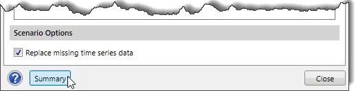
The Scenario Options section allows the user to replace the missing time series data.
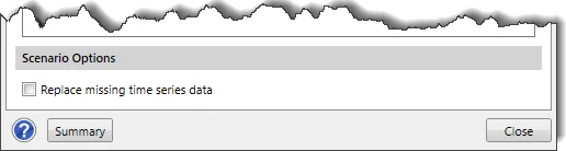
Checking the Replace missing time series data checkbox causes the software to substitute a zero value for the missing data values in the time series data during the simulation run. Note that if this option is left unchecked, any missing data will cause the simulation to stop, and an error message to be displayed.
The Duplicate Current Scenario command allows the user to make an identical copy of the current scenario (plan). Once the copy has been made, it is independent of the original and they do not interact.
To learn more about the Duplicate Current Scenario command, refer to this article in our knowledge base.
The Delete Scenarios command allows the user to delete data that no longer applies to the project and should not be submitted as part of the project. The following types of data can be removed: Scenario (Run), Basin, Meteorology, and Control Specification.
To learn more about the Delete Scenarios command, refer to this article in our knowledge base.
In the Scenario Manager dialog box, clicking on the [Summary] button will display an informational dialog box that provides information for all scenarios (plans) contained in a project. It includes a complete summary of all the scenarios, basin models, meteorologic models, control specifications, and other details of the current plan.
Alternatively, the user can view the scenario summary by selecting the Scenario Summary command from the list of Scenario Manager dropdown commands.
To learn more about the Scenario Summary command, refer to this article in our knowledge base.
GeoHECHMS can perform analysis on multiple scenarios (plans) at the same time. It is useful, for instance, when comparing storms that occur once every 100 years or 500 years. Computations on the multiple plans can then be performed sequentially (one immediately after the other) using the Multiple Scenarios command.
To learn more about the Multiple Scenarios command, refer to this article in our knowledge base.
After the computations have been performed, the software can display the results from multiple scenarios for all the HEC-HMS elements (i.e., subbasins, reaches, junctions, etc).
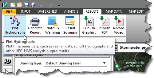
To view the output results, select the Plot Hydrographs command from the Results ribbon menu.
The Plot Hydrographs window will be displayed.
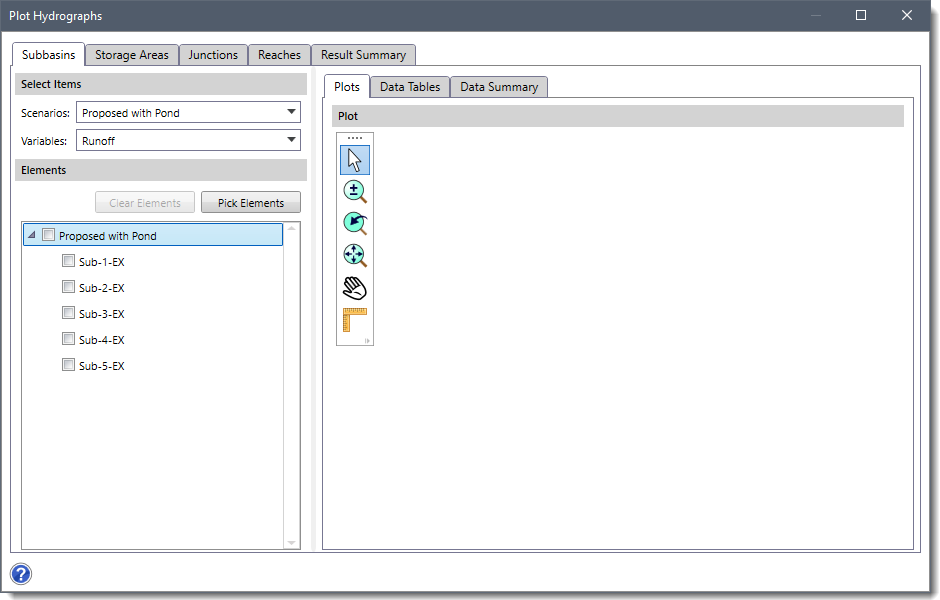
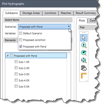
The above window has separate panels (i.e., Subbasins, Storage Areas, Junctions, Reaches, etc.) to show output results for each HEC-HMS element type present in the project. Within each element type panel, the user can select the preferred scenario from the Scenarios dropdown combo box of the Select Items panel.
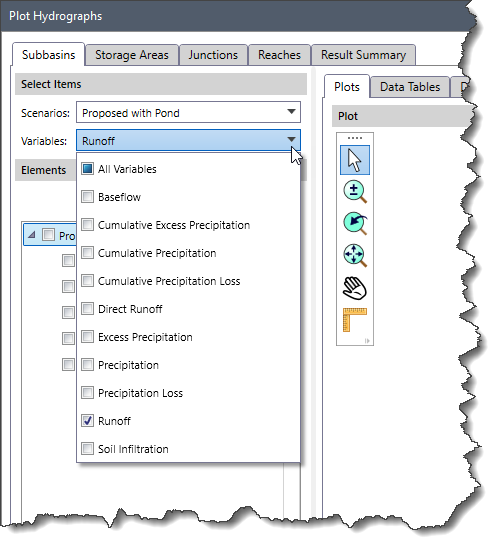
The Variables dropdown combo box allows the user to select the desired output variables associated with an element type whose results are to be displayed.
Note that the Variables dropdown combo box is not available in the Result Summary panel. The Result Summary panel displays the summary of the current HEC-HMS analysis results for each element (Subbasins, Storage Areas, Junctions, etc.) in tabular form.
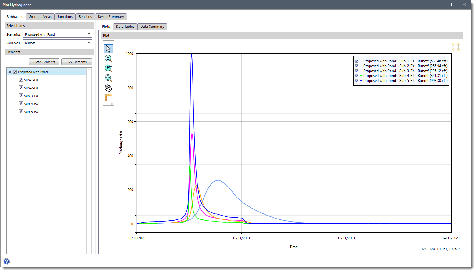
All the elements (corresponding to the element type) present in the HEC-HMS model of the selected scenario will be displayed under the Elements section. The user can check the checkbox corresponding to the preferred element(s) from the Elements section to see output results associated with them. Alternatively, the user can click the [Pick Elements] button to select the element(s) from the Map View. The user can click the [Clear Elements] button to clear the selected element(s). The output results related to the selected element(s) will be displayed under the Plots, Data Tables and Data Summary panels.


CivilGEO G2 Reviews
4.8/5.0 Rating, Over 230 Reviews

GeoHECRAS is recognized as the top Civil Engineering Design Software with an average of 4.8 out of 5.0 rating from over 230 real user reviews on G2.


We use cookies to give you the best online experience. By agreeing you accept the use of cookies in accordance with our cookie policy.
When you visit any web site, it may store or retrieve information on your browser, mostly in the form of cookies. Control your personal Cookie Services here.


