
Welcome to CivilGEO Knowledge Base
Welcome to CivilGEO Knowledge Base
A diversion is an element with two outflows, main and diverted, and one or more inflows. Inflow comes from other elements in the basin model. If there are multiple inflows, all inflows are added together before computing the outflow. A diversion can be used to represent weirs or pump stations that divert flow into canals or off-stream storage. The diversion element includes various methods for limiting the diverted flow that will be taken out of the channel. All flow that is not diverted becomes the main outflow. Diverted flow can be connected to an element that is computationally downstream or can simply be lost out of the system.
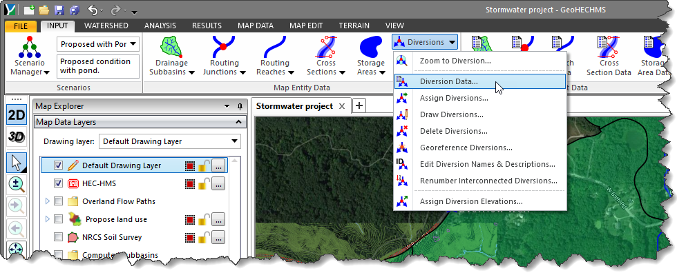
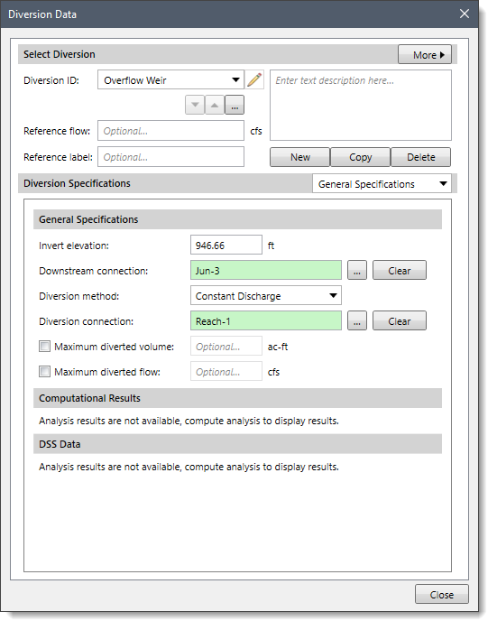
In GeoHECHMS, the diversion methods can be selected from the General Specifications section of the Diversion Data dialog box. Each diversion element may use a different method, or several diversions may use the same method.
Follow the steps below to select a diversion method:
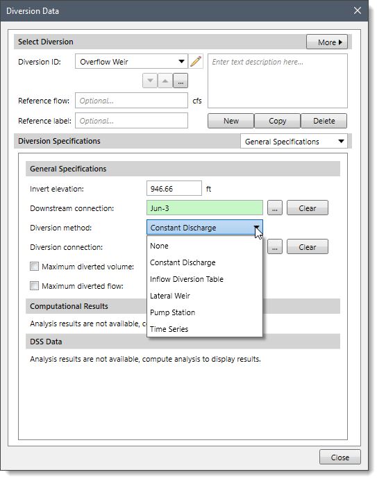
The following sections describe the different diversion methods and how to enter the parameters for each method in the Diversion Data panel.
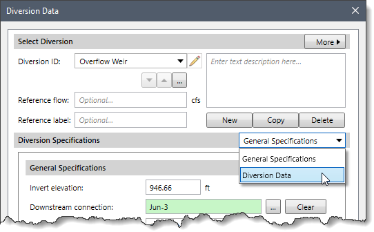
When None is selected for the diversion method, the Diversion Data dropdown combo box entry is disabled (i.e., grayed out).
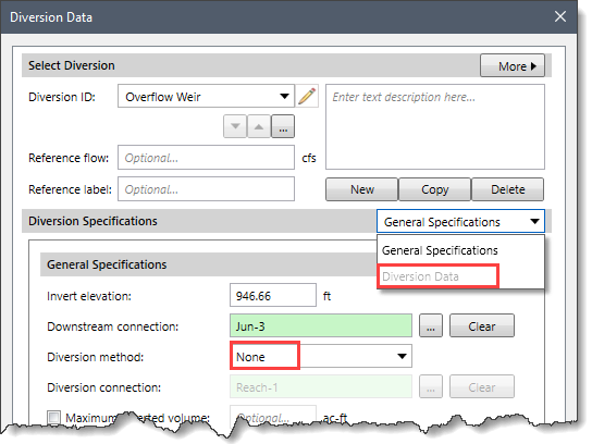
If None is selected for the diversion method, the diversion will pass all flow down the main connection and no flow will be diverted.
This method uses a constant diversion flowrate for the entire simulation. It is best suited to a particular event simulation when the diversion flow is more likely to be constant. If the diversion flowrate changes during the year according to a reliable pattern, the optional percentage pattern can be used to adjust the constant rate throughout the year.
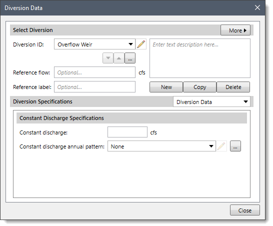
When Constant Discharge is selected for the diversion method, the following data panel will be displayed:
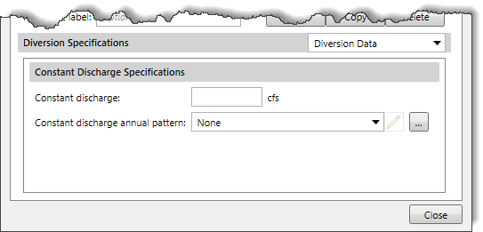
The following input parameters are provided in the data panel:
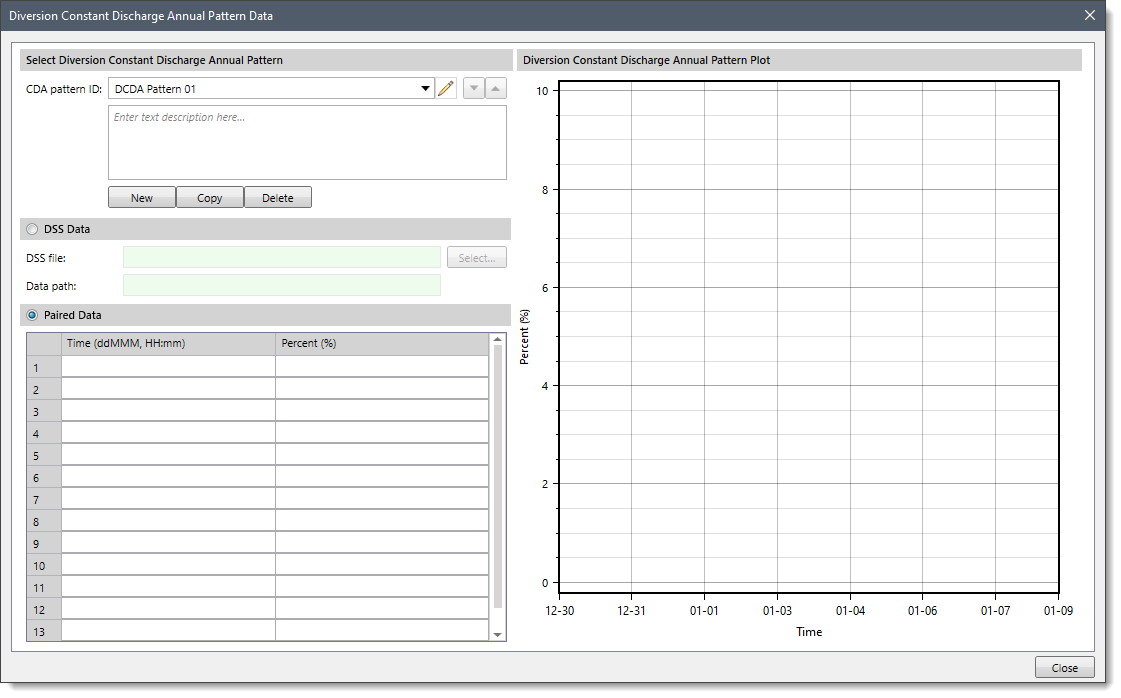 Note that the user can define a percentage value ranging from 0 to 1000%.
This method uses a functional relationship between inflow and diverted flow to determine the amount of flow that should be diverted for each time step. The defined range of inflows should cover the complete range of total inflow from the upstream elements. Usually, the first defined inflow value is defined as zero. The last defined inflow value should be greater than the maximum anticipated inflow into the diversion element. Diversion flow is a dependent variable and must be specified for each corresponding inflow value.
When the Inflow Diversion Table is selected for the diversion method, the following data panel will be displayed:
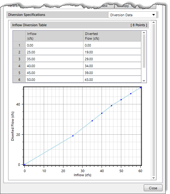
The following input parameters are provided in the data panel:
The only method currently available for computing flow over the lateral weir is the broad-crested spillway method. Flow depth in the channel is computed using a rating curve. It is assumed to be level with a uniform head along the length of the weir computed using the rating curve. Tailwater is similarly computed using a rating curve that represents the characteristics of the area where the weir discharges the diverted flow.
When Lateral Weir is selected for the diversion method, the following data panel will be displayed:
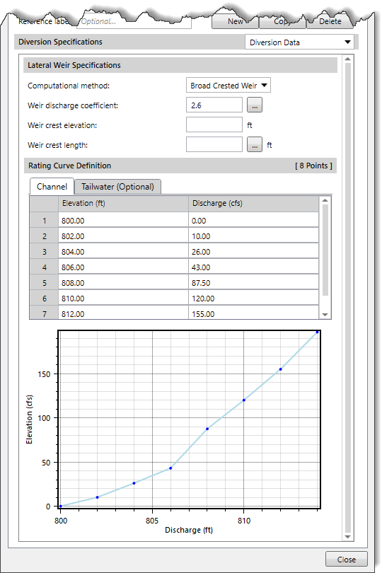
The following input parameters are provided in the data panel:
This section allows the user to define the rating curve data. Any defined rating curve should provide the stage for the entire range of inflows that will occur during a simulation. The defined curve must be monotonically increasing.
The following tabbed panels are provided:
This panel allows the user to define a channel rating curve. It represents the elevation versus discharge at the upstream side of the flow diversion.
The following entries are used for defining the rating curve:
This optional panel allows the user to define a tailwater rating curve. The rating curve should define the tailwater stage in the area where the diverted flow is discharged. It is used to automatically account for the submergence of the weir. If there is no tailwater rating curve defined, then the software computes the flow over the weir assuming no tailwater influence.
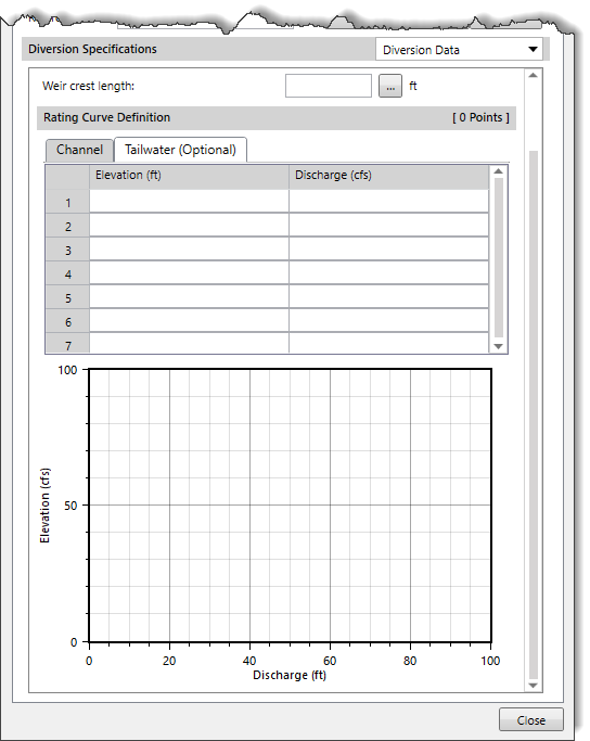
Note that the entries of the Tailwater (Optional) panel are similar to that of the Channel panel.
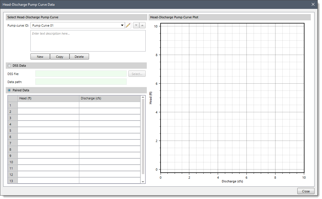
A pump station diversion method is designed to represent one or more pump units extracting water from the main channel and discharging it into a diversion. The head-discharge curve describes the pumping capability of the pump as a function of the total head. The total head is the sum of the equipment loss and the dynamic head. The dynamic head is first estimated as the difference between the water surface elevation in the channel and the line elevation. If the water surface elevation is above the line elevation, then the estimated value will be zero. Secondarily, the estimate is adjusted for tailwater submergence. This second stage is only necessary if an optional tailwater rating curve is specified. When specified, the tailwater water surface elevation is compared to the line elevation. If the tailwater exceeds the line elevation, then the depth of submergence over the line elevation is added to the initial estimate of the dynamic head. The head-discharge curve is used to calculate the diverted flow given the calculated total head.
When Pump Station is selected for the diversion method, the following data panel will be displayed:
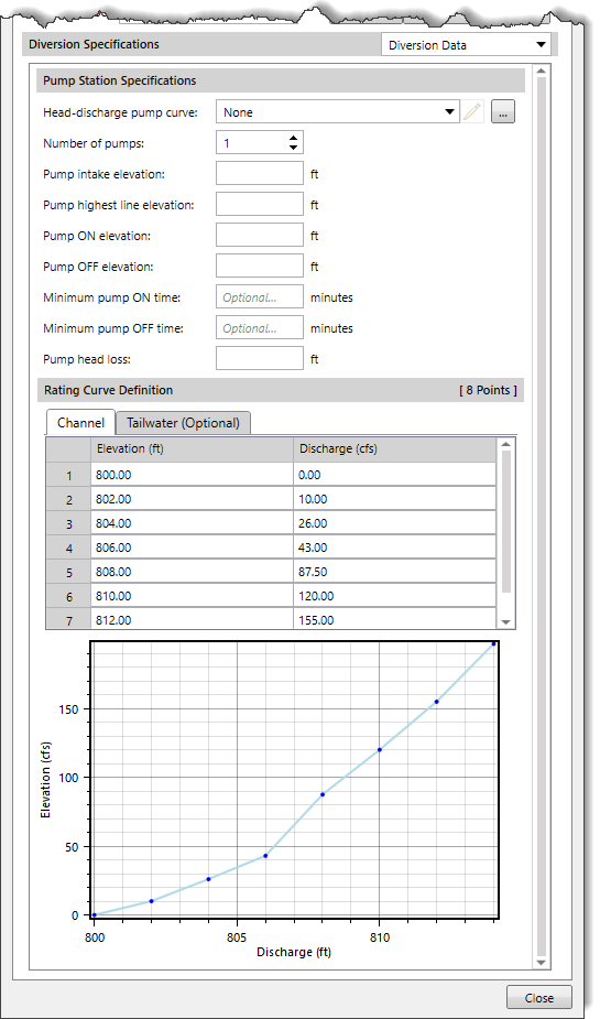
The following input parameters are provided in the data panel:
Note that the Rating Curve Definition section of the Pump Station diversion method is similar to that of the Rating Curve Definition section of the Lateral Weir diversion method.
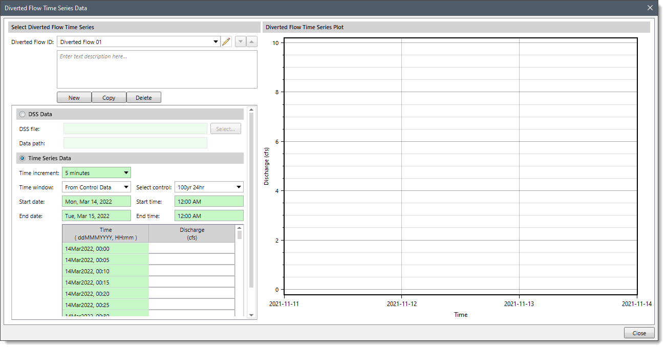
The time series flow diversion method is designed for situations where the flow diverted from the channel is measured with a flow gage. This method allows the user to enter the time series of discharges that are diverted from the channel. If the specified diversion discharge exceeds the total inflow to the diversion, then the diversion will be limited to the inflow volume.
When Time Series is selected for the diversion method, the following data panel will be displayed:
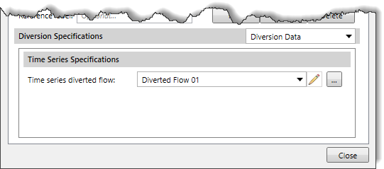
The following input parameter is provided in the data panel:
| Method | Pros | Cons |
|---|---|---|
| Constant Discharge | ||
| Inflow Diversion Table | ||
| Lateral Weir | ||
| Pump Station | ||
| Time Series |


CivilGEO G2 Reviews
4.8/5.0 Rating, Over 230 Reviews

GeoHECRAS is recognized as the top Civil Engineering Design Software with an average of 4.8 out of 5.0 rating from over 230 real user reviews on G2.


We use cookies to give you the best online experience. By agreeing you accept the use of cookies in accordance with our cookie policy.
When you visit any web site, it may store or retrieve information on your browser, mostly in the form of cookies. Control your personal Cookie Services here.


