The Delineate Catch Basin command allows the user to delineate the drainage areas corresponding to selected catch basin inlets for the defined terrain surface.
Follow the steps given below to use the Delineate Catch Basin command:
- From the Watershed ribbon menu, select the Delineate Catch Basin command.
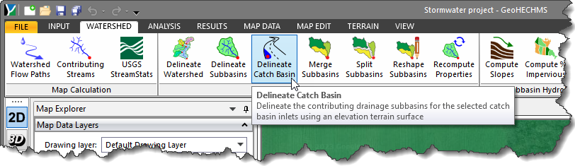
- The Delineate Catch Basin dialog box will be displayed.
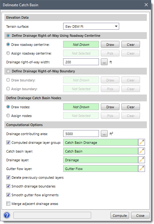
The following sections describe the Delineate Catch Basin command and how to interact with the above dialog box.
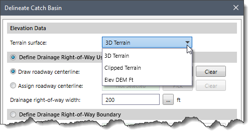
Elevation Data
This section allows the user to select the elevation terrain surface. The Terrain surface dropdown combo box lists all the terrain surfaces that are already added to the project.
Defining Drainage Right-of-Way Using Roadway Centerline
This section allows the user to define the drainage right-of-way using the roadway centerline. The user can define the drainage right-of-way by manually drawing the roadway centerline or selecting the already drawn roadway centerline from the Map View.
To draw the roadway centerline on the Map View, follow the steps below:
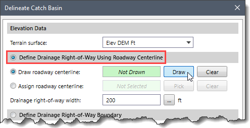
- Select Define Drainage Right-of-Way Using Roadway Centerline radio button. Note that this radio button option is selected by default.
- Select the Draw roadway centerline radio button option and click the [Draw] button.
- The Delineate Catch Basin dialog box will temporarily disappear, and a prompt will be displayed on the status bar instructing the user what to do next.
- Draw the roadway centerline on the Map View. While drawing the roadway centerline, the user can use the [Ctrl] key for the straight segment.
- Once finished, press the [Enter] key or right-click and select Done from the displayed context menu.
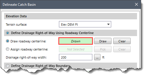
- The Delineate Catch Basin dialog box will be redisplayed and the status of the Draw roadway centerline read-only field will be changed from Not Drawn to Drawn.
- The [Clear] button can be used to remove any previously defined roadway centerline in order to redo the process.
To assign the roadway centerline from the Map View, follow the steps below:
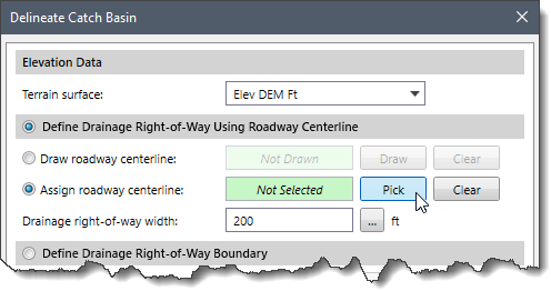
- Select the Assign roadway centerline radio button option and then click the [Pick] button.
- The Delineate Catch Basin dialog box will temporarily disappear, and a prompt will be displayed on the status bar instructing the user what to do next.
- Select the roadway centerline from the Map View.
- Once finished, press the [Enter] key or right-click and select Done from the displayed context menu.
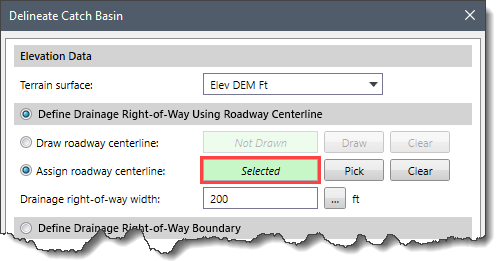
- The Delineate Catch Basin dialog box will be redisplayed and the status of the Assign roadway centerline read-only field will be changed from Not Selected to Selected.
- The [Clear] button can be used to remove any previously selected roadway centerline in order to redo the process.
The Drainage right-of-way width input field allows the user to define the buffer value for the width of the roadways to compute the drainage area. Using this value, the software can detect the roadway centerline and maintain the correct drainage network. The following image represents a typical “Right-of-Way”.
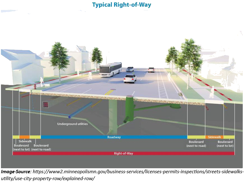
By default, the software uses a value of 200 ft. The user can enter the buffer value manually or click the […] button to measure the approximate right-of-way width that would be encountered from the Map View.
Defining Drainage Right-of-Way Boundary
This section allows the user to define the drainage right-of-way boundary. The user can define the drainage right-of-way boundary by manually drawing the polygon or selecting the already drawn polygon from the Map View.
To draw the drainage right of way boundary on the Map View, follow the steps below:
- Select the Define Drainage Right-of-Way Using Boundary radio button to enable this section.
- Select the Draw boundary radio button option and then click the [Draw] button.

- The Delineate Catch Basin dialog box will temporarily disappear, and a prompt will be displayed on the status bar instructing the user what to do next.
- Draw the drainage boundary on the Map View. While drawing the drainage boundary, the user can use the [Ctrl] key for the straight segment.
- Once finished, press the [Enter] key or right-click and select Done from the displayed context menu.
- The Delineate Catch Basin dialog box will be redisplayed and the status of the Draw boundary read-only field will be changed from Not Drawn to Drawn.

- The [Clear] button can be used to remove any previously defined right-of-way polygon in order to redo the process.
To assign a drainage right of way boundary from the Map View, follow the steps below:
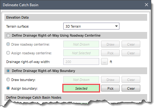
- Select the Assign boundary radio button option and then click the [Pick] button.

- The Delineate Catch Basin dialog box will temporarily disappear, and a prompt will be displayed on the status bar instructing the user what to do next.
- Select the polygon from the Map View.
- Once finished, press the [Enter] key or right-click and select Done from the displayed context menu.
- The Delineate Catch Basin dialog box will be redisplayed and the status of the Assign boundary read-only field will be changed from Not Selected to Selected.
- The [Clear] button can be used to remove any previously selected right-of-way polygon in order to redo the process.
Defining Drainage Catch Basin Nodes
This section allows the user to define the catch basin nodes. The user can define the catch basin nodes by manually drawing the nodes or selecting the already drawn nodes from the Map View to assign them as catch basin nodes.
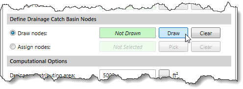
To draw the catch basin nodes on the Map View, follow the steps below:
- Select the Draw nodes radio button option and then click the [Draw] button.
- The Delineate Catch Basin dialog box will temporarily disappear, and a prompt will be displayed on the status bar instructing the user what to do next.
- Draw the catch basin nodes on the Map View.
- Once finished, press the [Enter] key or right-click and select Done from the displayed context menu.
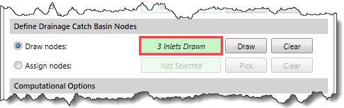
- The Delineate Catch Basin dialog box will be redisplayed, and the count of drawn inlet points will be shown in the Draw nodes read-only field.
- The [Clear] button can be used to remove any previously defined catch basin nodes in order to redo the process.
To assign catch basin nodes from the Map View, follow the steps below:
- Select the Assign nodes radio button option and then click the [Pick] button.
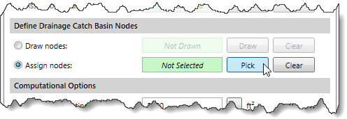
- The Delineate Catch Basin dialog box will temporarily disappear, and a prompt will be displayed on the status bar instructing the user what to do next.
- Select the inlet points from the Map View.
- Once finished, press the [Enter] key or right-click and select Done from the displayed context menu.
- The Delineate Catch Basin dialog box will be redisplayed, and the count of selected inlet points will be shown in the Assign nodes read-only field.
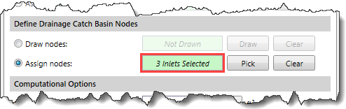
- The [Clear] button can be used to remove any previously selected catch basin nodes in order to redo the process.
Computational Options
This section provides multiple options that affect the catch basin’s appearance and delineation process.
The following options are provided under the Computational Options section:
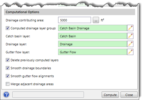
- The Drainage contributing area entry field allows the user to define the extent of the drainage accumulation area. This is the area that must be amassed for runoff to be considered as gutter flow. By default, the software uses a value of 5000 square feet. The user can enter a different value for the drainage accumulation area or click the […] button to interactively measure the catch basin contributing area threshold from the Map View.
- Checking the Computed drainage layer group checkbox allows the user to group the catch basin, drainage, and gutter flow layers into one layer group in the Map Data Layers panel. If this checkbox is left unchecked, the software will put the catch basin, drainage, and gutter flow layers separately in the Map Data Layers panel. The user can define the names of these layers by clicking the corresponding pen icons next to the layer name.
- Checking the Delete previously computed layers checkbox causes the software to delete any previously computed drainage layers. By default, this checkbox is checked.
- Checking the Smooth drainage boundaries checkbox causes the software to smooth the boundaries of delineated catch basins. By default, this checkbox is checked.
- Checking the Smooth gutter flow alignments checkbox causes the software to smooth the gutter flow alignment network. By default, this checkbox is checked.
- Checking the Merge adjacent drainage area checkbox causes the software to merge smaller adjacent drainage areas into a larger drainage area.
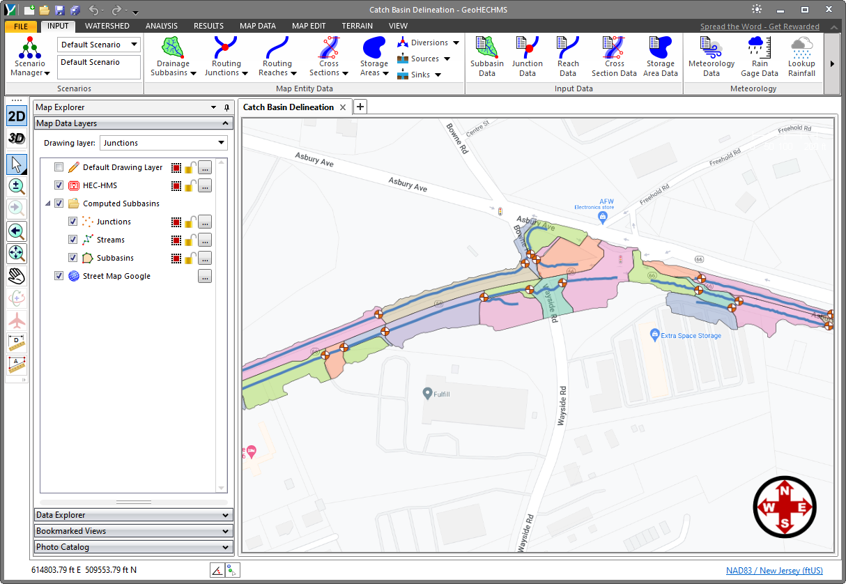
Computing Catch Basin Delineation
When all the options in the Delineate Catch Basin dialog box have been defined, click the [Compute] button. The delineation process will begin. On completion, the delineated catch basin network will be displayed in the Map View, as shown below.