Lateral structures are hydraulic structures that run parallel to the river course and are used to model flow being transferred between a river and adjacent elements, such as another river reach, storage area, or 2D flow area. Lateral structures can be used to divert water, control flow, or provide access to a river reach. They can be modeled as culverts, weirs, gated spillways, diversion rating curves, and an outlet time series.
The user can set up a single lateral weir, a weir and separate set of gates, a weir and group of culverts, or any combination of a weir, gates, culverts, rating curves, and a time series outlet. The gated spillways can have either radial gates, vertical lift gates, overflow gates, or user-defined gate curves. The spillway crest of the gates can be modeled as either an ogee shape, broad crested weir, or sharp crested weir shape. The culverts can be any of the available shapes from the standard HEC-RAS culvert capability. The diversion rating curve can be used alone or in conjunction with the other hydraulic outlet types. The rating curve can be used to represent a structure or a particular outlet that could not be directly modeled with HEC-RAS.
The lateral structure should be created in the downstream direction along the edges of cross sections. To learn how to create a lateral structure, refer to this article in our knowledge base. After creating lateral structures, the user can use the Lateral Structure Data command to define the lateral structure data, connection data, overflow weir, culverts, gate openings, rating curves, and more.
This article describes how to use the Lateral Structure Data command in GeoHECRAS software.
Follow the steps below to view or modify lateral structure data:
- From the Input ribbon menu, select the Lateral Structure Data command.
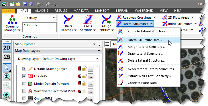
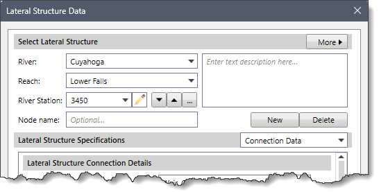
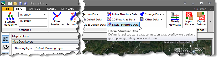 Alternatively, the user can either double-click on the lateral structure from the Map View or choose the Lateral Structure Data command from the Lateral Structures dropdown menu of the Input ribbon menu as shown below.
- The Lateral Structure Data dialog box will be displayed.
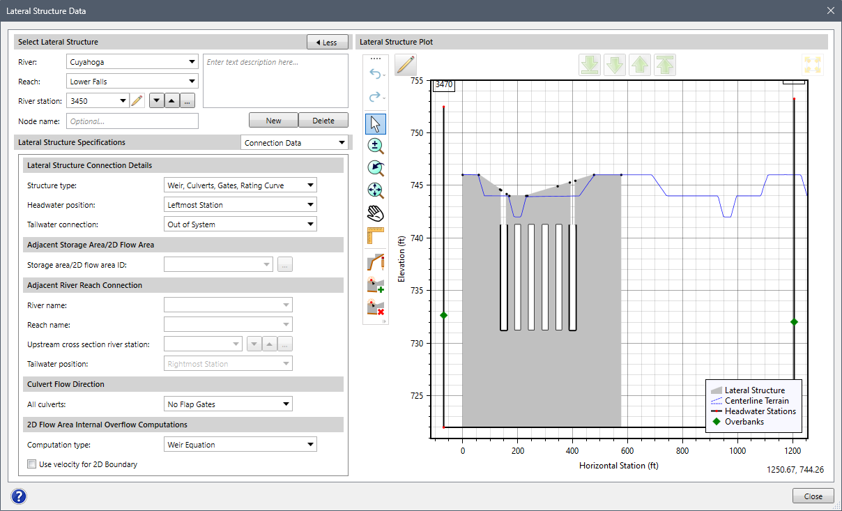
The following sections describe how to use the Lateral Structure Data command and interact with the above dialog box.
Selecting Lateral Structure
This section allows the user to specify the river, reach, and corresponding river station along which the lateral structure is drawn in order to define the lateral structure data. The user can create a new lateral structure, copy existing lateral structure data to a new lateral structure, and delete a lateral structure.
This section requires the following data:
- River
This dropdown combo box lists all of the currently defined rivers in the project. The user can select the desired river name from the dropdown list. Note that when the user changes a river, the Reach dropdown combo box also updates to show a valid corresponding river reach.
- Reach
This dropdown combo box lists all of the currently defined reaches that correspond to the selected river.
- River station
This editable dropdown combo box lists all the lateral structure river stations defined in the project that correspond to the selected reach. Click the pencil icon to edit the lateral structure river station. The Up and Down arrow buttons adjacent to the dropdown combo box allow the user to switch between the next adjacent downstream and upstream lateral structure. Note that the up and down arrow buttons will be disabled (i.e., grayed out) if the project contains only one lateral structure. Alternatively, the user can click the […] button to select the lateral structure from the Map View.
- Node name
This entry field allows the user to assign an optional text label to the current lateral structure.
- Description
This text field allows the user to enter additional information that describes the selected lateral structure.
- New
The [New] button allows the user to draw a new lateral structure on the Map View. Note that the newly created lateral structure name must be unique.
- Copy
The [Copy] button allows the user to create a copy of the current lateral structure.
- Delete
The [Delete] button allows the user to delete the current lateral structure from the project.
- Less/More
The [< Less] and [More >] buttons at the Select Lateral Structure header allow the user to hide and display the right side of the dialog box containing the Lateral Structure Plot. This causes the dialog box to diminish in size when the user does not want to see the plot view.
Lateral Structure Specifications
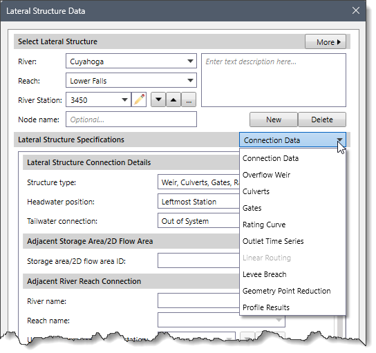
The Lateral Structure Specifications dropdown combo box contains several data panel entries that allow the user to define lateral structure data. The following data panel entries are listed in the dropdown combo box:
- Connection Data
- Overflow Weir
- Culverts
- Gates
- Rating Curve
- Outlet Time Series
- Linear Routing
- Levee Breach
- Geometry Point Reduction
- Profile Results
Connection Data Panel
This panel provides connection details for the selected lateral structure. Note that by default, the Connection Data panel is shown when the Lateral Structure Data command is selected.
Lateral Structure Connection Details
This section is used to define the connection details for the selected lateral structure.
This section requires the following data:
- Structure type
This dropdown combo box allows the user to select the type of routing that will be used for the selected lateral structure. The following options are available:
- Weir/Gates/Culverts/Rating Curves – This option is used where the software calculates the flow across the structure by performing detailed hydraulic calculations for the weir, gated spillways, culverts, and any rating curve.
- Linear Routing – This option is a simplified method in which the user enters a linear routing coefficient. This coefficient can vary between 0.0 and 1.0, with 1.0 representing the maximum flow over the structure and 0.0 representing no flow. The linear routing method is a simple storage accounting method. This method can be very useful when the user has many lateral structures connected to storage areas, and a detailed flow calculation over each structure is not necessary.
Based on the type of routing selected in the Structure type dropdown combo box, the other data panel entries in the Lateral Structure Specifications dropdown combo box get enabled or disabled.
- Headwater position
This dropdown combo box is used to define where the headwater section of the lateral structure is spatially located relative to the river reach. The following options are available:
- Leftmost Station – Located at the leftmost station of the cross section
- Left Bank – Located at the left bank of the river channel
- Right Bank – Located at the right bank of the river channel
- Rightmost Station – Located at the rightmost station of the cross section
- Tailwater connection
This dropdown combo box is used to define what the lateral structure is connected to (i.e., where the water leaving from the main river will be going). The following options are available:
- Out of System – On selecting this option, no other information is required.
- Adjacent SA/2D Flow Area – On selecting this option, the user is required to select a storage area or a 2D flow area from a dropdown list of the currently defined storage areas.
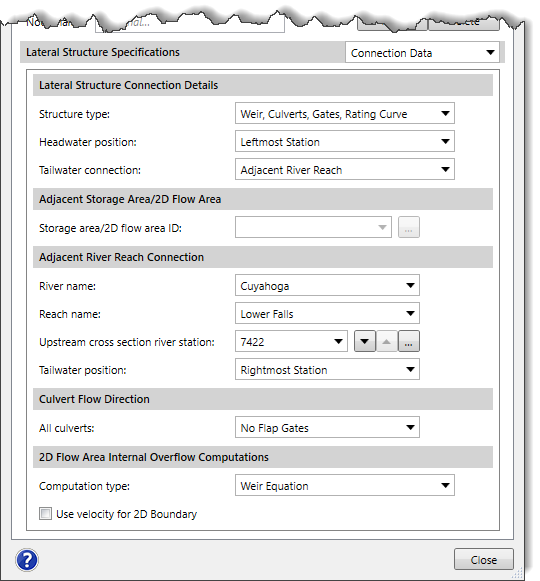
- Adjacent River Reach – On selecting this option, the user is required to select the river, reach, and range of cross sections from which the lateral structure is connected.
Based on the tailwater connection selected in the Tailwater connection dropdown combo box, the other sections of the Connection Data panel get enabled or disabled.
Adjacent Storage Area/2D Flow Area
This section is used to define the connection (with the current or a different river reach) to an adjacent storage area/2D flow area to the lateral structure. Note that this section is enabled when the Adjacent SA/2D Flow Area option is selected in the Tailwater Connection dropdown combo box of the Lateral Structure Connection Details section. Otherwise, it is disabled (i.e., grayed out).
The Storage area/2D flow area ID dropdown combo box lists all the storage areas/2D flow areas defined in the project. Alternatively, the user can click the […] pick button to select the storage area or 2D flow area from the Map View.
Adjacent River Reach Connection
This section is used to define the connection (with the current or a different river reach) to an adjacent river reach to the lateral structure. Note that this section is enabled when the Adjacent River Reach option is selected in the Tailwater Connection dropdown combo box of the Lateral Structure Connection Details section. Otherwise, it is disabled (i.e., grayed out).
This section requires the following data:
- River
This dropdown combo box lists all the rivers defined in the project. The user can select the desired river name from the dropdown combo box. When the user changes a river, the Reach dropdown combo box automatically updates to display a valid corresponding river reach.
- Reach
This dropdown combo box lists all the reaches defined in the project that correspond to the selected river.
- Upstream cross section river station
This dropdown combo box lists all the cross sections defined in the project that correspond to the selected reach. This entry defines the upstream most cross section associated with the adjacent river reach that the lateral structure is connected with.
In addition, the Up and Down arrow buttons adjacent to the dropdown combo box allow the user to switch between the next adjacent downstream and upstream cross section. Alternatively, the user can click the […] pick button to select the cross section from the Map View.
- Tailwater position
This dropdown combo box is used to define where the tailwater section of the lateral structure is spatially located relative to the cross sections of the selected adjacent river reach. The following options are available:
- Leftmost Station – Located at the leftmost station of the cross section
- Left Bank – Located at the left bank of the river channel
- Right Bank – Located at the right bank of the river channel
- Rightmost Station – Located at the rightmost station of the cross section
Culvert Flow Direction
This section is used to define the culvert flow direction for the selected lateral structure. It only affects the flow through the culverts, not flow through the weir or the gated structures.
The All culverts dropdown combo box provides the following options to describe culvert flow:
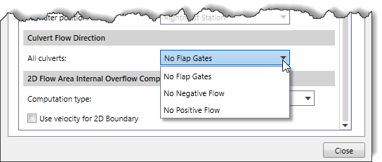
- No Flap Gates – This means that flow can move in both directions through the culverts.
- No Negative Flow – This means that flow can only move in the positive flow direction through the culverts (downstream).
- No Positive Flow – This means that flow can only move in the negative direction through the culverts (upstream).
2D Flow Area Internal Overflow Computation
This section is used to control which equations are used to compute the flow across a lateral structure.
This section requires the following data:
- Computation Type
This dropdown combo box allows the user to select the overflow computational method. The following options are available:
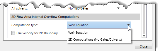
- Weir Equation – This option is used to simulate the flow over a lateral structure, such as a weir, in a river or channel. By default, this option is selected.
- 2D Computations (No Gates/Culverts) – This option is used to figure out how much flow is going across the lateral structure and in which direction. When this option is selected, an average water surface elevation is computed on the 1D riverside, in front of each 2D cell that is connected with the lateral structure. This water surface is then applied as a stage boundary condition for each individual cell of the 2D area. So, if water is above the weir profile, and the elevation is higher in the 1D river than the 2D cell, then water will go from the 1D river to the 2D cell. If the 2D cell is higher than the 1D river, then water will go from the 2D cell to the 1D river. If the water is below the elevation of the weir, then the flow is zero for that cell.
- Use velocity for 2D Boundary
This checkbox option is used only when a lateral structure is connected to a 2D flow area. In general, for this type of flow connection, flow is computed across the structure and passes into and out of the 2D cells, and no velocity is considered at the face. In addition to flow, a velocity is computed and applied to the face of the 2D cells. If this option is selected, it will produce more accurate flow velocities into the 2D flow area but may be less stable. By default, this checkbox option is unchecked.
Overflow Weir Panel
This panel allows the user to enter the embankment and weir geometry data for the selected lateral structure. These data are used to describe the embankment in which the outlets will be placed, as well as any uncontrolled weirs.
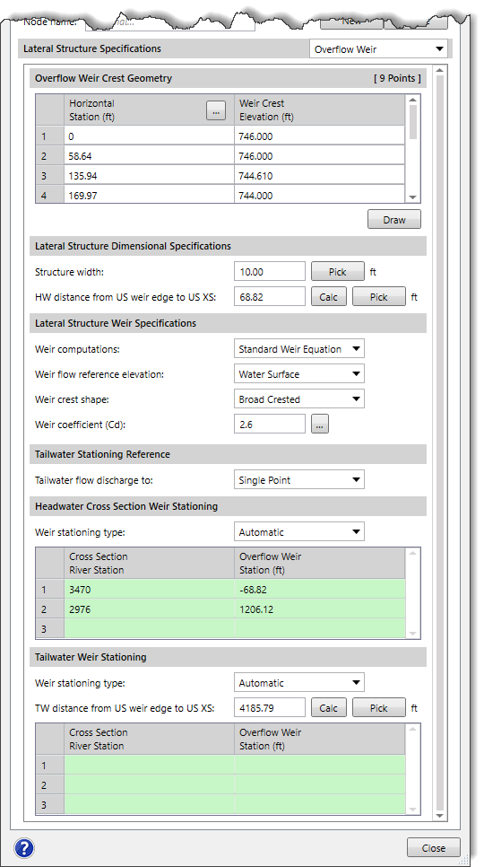
Overflow Weir Crest Geometry
This section provides a table for entering and editing lateral structure overflow weir geometry. The geometry of the overflow weir is entered from upstream to downstream in stationing. The user enters stations and corresponding elevations of the top of the embankment and weir. The stationing is relative, so it can be started at any number (i.e., 0, 100, etc.). The stations and elevations should be entered from the upstream end to the downstream end of the lateral structure. Everything below the defined crest geometry elevations is considered solid ground.
By default, the lateral structure will be lined up with the river reach by comparing the stationing entered with the reach lengths of the river reach. If the lateral structure is located at the leftmost stationing of the reach, then the left overbank flow lengths are used. If the lateral structure is located at the right or left bank station of the main channel, then the main channel flow lengths will be used. If the lateral structure is located at the rightmost stationing of the reach, then the right overbank flow lengths are used.
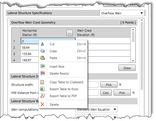
The user can also draw the weir geometry for the lateral structure on the Lateral Structure Plot using the [Draw] button. Click the [Draw] button, and then draw the weir geometry on the Lateral Structure Plot. When finished, the user can press the [Enter] key or right-click and select Done from the displayed context menu. The software will then automatically compute the overflow weir geometry and fill the computed values in the table.
The right-click context menu of the table displays the commands to cut, copy, and paste cells, and insert and delete rows to and from the table. In addition, the user can also copy the grid data to the clipboard or export it as a Microsoft Excel or PDF document.
Lateral Structure Dimensional Specifications
This section defines the dimensions of the lateral structure.
This section requires the following data:
- Structure width
This entry field is used to define the width of the lateral structure (measured along the flow direction). Alternatively, the user can click the [Pick] button to interactively measure the structure width from the Map View.
Note that this value will only be used for graphical plotting and does not have any effect on the computations.
- HW distance from US weir edge to US XS
This entry field is used to define the distance from the upstream end of the overflow weir headwater section of the lateral structure and the cross section immediately upstream of the structure on the current river reach. Alternatively, the user can click the [Pick] button to interactively measure this distance from the Map View. Clicking the [Calc] button causes the software to automatically calculate the headwater distance from the upstream weir edge to the next upstream cross section.
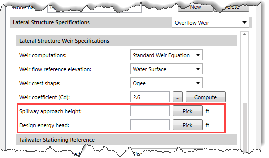
Lateral Structure Weir Specifications
This section defines the overflow weir specifications of the lateral structure.
This section requires the following data:
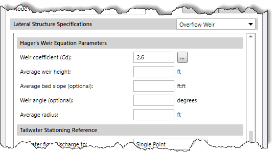
Hager’s Weir Equation Parameters
This section defines the parameters for Hager’s weir equation. Note that this section is only available when Hager’s Weir Equation is selected in the Weir computation dropdown combo box of the Lateral Structure Specifications section.
This section requires the following data:
- Weir coefficient (Cd)
This entry field is used to define the weir coefficient that will be used for the first iteration of trying the Hager lateral weir equation. The equation is iterative and requires hydraulic results in order to make a weir coefficient calculation. The defined weir coefficient is only used for the first guess at the hydraulic computations. Clicking on the […] button will display a weir coefficient reference dialog box.
- Average weir height
This entry field is used to define the average height (not elevation) of the weir above the ground.
- Average bed slope(optional)
This entry field is used to define the average slope of the stream bed in the river reach containing the lateral structure. If this entry is left blank, HEC-RAS will compute the slope by estimating an average bed elevation for each cross section and then compute the slope from the average bed elevation. The average bed elevation of the cross sections is obtained by subtracting the hydraulic depth from the water surface elevation.
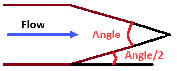
- Weir angle(optional)
This entry field is used to define the angle (in degrees) for the lateral structure overflow weir. If the overflow weir is parallel to the stream, the angle is assumed to be zero. If the weir is angled inwards towards the center of the river, an angle is required. This is used for channels that have a contraction where the weir flow is allowed to go over the contracted section. A diagram showing the angle is shown below.
- Average radius
This entry field is used to define the average radius of the ogee weir for Hager’s equation. This field is enabled when the Ogee is selected in the Weir crest shape dropdown combo box of the Lateral Structure Dimensional Specifications section. Otherwise, it is disabled (i.e., grayed out).
Tailwater Stationing Reference
This section defines how the lateral structure discharges to the adjacent river reach cross sections. Note that this section is enabled when the Adjacent River Reach is selected in the Tailwater connection dropdown combo box of the Connection Data panel. Otherwise, it is disabled (i.e., grayed out).
The Tailwater flow discharged to dropdown combo box is used to define where the lateral structure overflow weir flow is discharged in the tailwater reach. The following options are available:
- Single Point (default) – This option is used when the discharge is set to go into a single point.
- Multiple Cross Sections – This option is used when the discharge is spread out over multiple cross sections.
Headwater Cross Section Weir Stationing
This section defines the lateral structure headwater cross section weir stationing.
This section contains a table. By default, the table will show the weir stationing that intersects with the cross sections in the river reach where the lateral structure is defined. The software automatically aligns the weir with the cross sections in the reach based on the weir stationing and the reach lengths in the cross sections (i.e., left overbank, main channel, or right overbank reach lengths). However, if the user does not like how the defined weir intersects with the cross sections in the reach, the user can define their own intersection points by entering the desired weir stationing to intersect with each of the cross sections in the reach. Water surface elevations for the lateral structure will then be interpolated based on user-defined stationing.
This section requires the following data:
- Weir stationing type
This dropdown combo box is used to define how the weir stationing on the headwater side of the lateral structure overflow weir is to be defined. The following options are available:
- Automatic (default) – On selecting this option, the table below it in the section becomes read-only.
- Manual Defined – On selecting this option, the table below it in the section becomes editable allowing the user to define their own intersection points.
- Cross Section River Station
This column lists the cross sections that are adjacent to the lateral structure, from just upstream of the lateral structure river station, and then on downstream to the end of the river reach.
- Overflow Weir Station
This column defines the weir stationing for the headwater overflow weir crest geometry in relation to the current river reach cross section river stationing.
Tailwater Weir Stationing
This section defines the lateral structure tailwater cross section weir stationing.
This section contains a table. The table can be used to manually line up the connected weir to either the 2D flow area or cross sections in another reach in a user-controlled manner. By default, the weir is lined up to any 2D flow area or cross sections of another river reach that it is connected to. However, the user can manually define where the stationing of the weir hits the 2D flow area face points or cross sections. If this option is used, the user must completely define where the entire length of the weir intersects the various tailwater cross sections or 2D flow area.
This section requires the following data:
- Weir stationing type
This dropdown combo box is used to define how the weir stationing on the tailwater side of the lateral structure overflow weir is to be defined. The following options are available:
- Automatic (default) – On selecting this option, the table below it in the section becomes read-only.
- Manual Defined – On selecting this option, the table below it in the section becomes editable allowing the user to define where the stationing of the weir hits the tailwater cross sections or 2D flow area face points.
- TW distance from US weir edge to US XS
This entry field is used to specify the distance from the upstream end of the overflow weir tailwater section of the lateral structure and the cross section immediately upstream of the structure on the adjacent river reach. Alternatively, the user can click the [Pick] button to interactively measure this distance from the Map View. Clicking the [Calc] button causes the software to automatically calculate the tailwater distance from the upstream weir edge to the next upstream cross section.
- Cross Section River Station
This column lists the cross sections that are adjacent to the lateral structure, from just upstream of the lateral structure river station, and then on downstream to the end of the river reach.
- Overflow Weir Station(ft)
This column defines the weir stationing for the tailwater overflow weir crest geometry in relation to the adjacent river reach cross section river stationing.
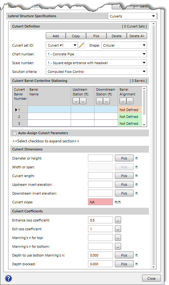
Culverts Panel
This panel is used to define the culvert for the selected lateral structure. Refer to this article in our knowledge base to learn how to define culverts using the Culverts panel.
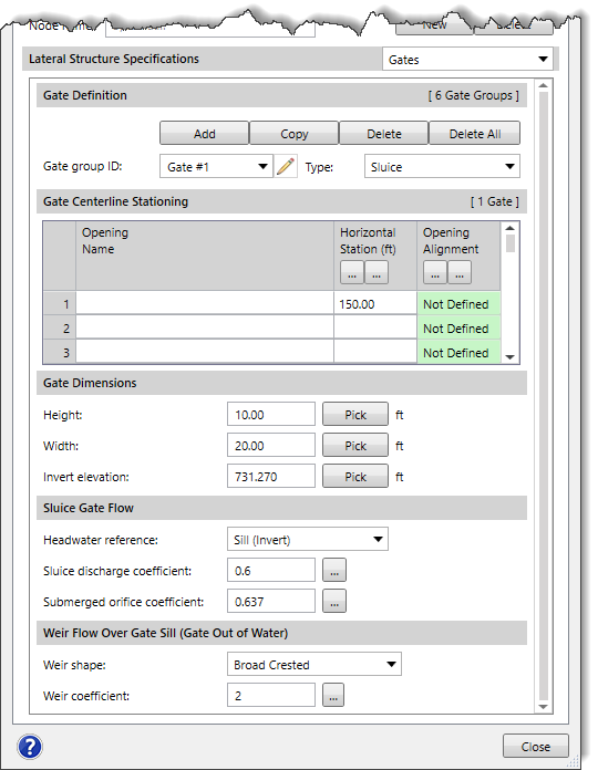
Gates Panel
This panel allows the user to add gates to the lateral structure. These can be used to represent flow diversions or locations where a mobile flood gate is rolled into place across a roadway or railway to maintain the levee during a flood. Refer to this article in our knowledge base to learn how to define gates using the Gates panel.
Rating Curve Panel
This panel provides the rating curve specifications for the selected lateral structures. The rating curve can be used alone, or in conjunction with the other lateral structure outlet types (i.e., overflow weir, culverts, and gates) to represent the diversion of flow from the main channel to the lateral structure. Generally, a rating curve can be used to represent a structure or a particular outlet that could not be adequately modeled with HEC-RAS. The rating curve removes flow from the main river reach and diverts it through the lateral structure.
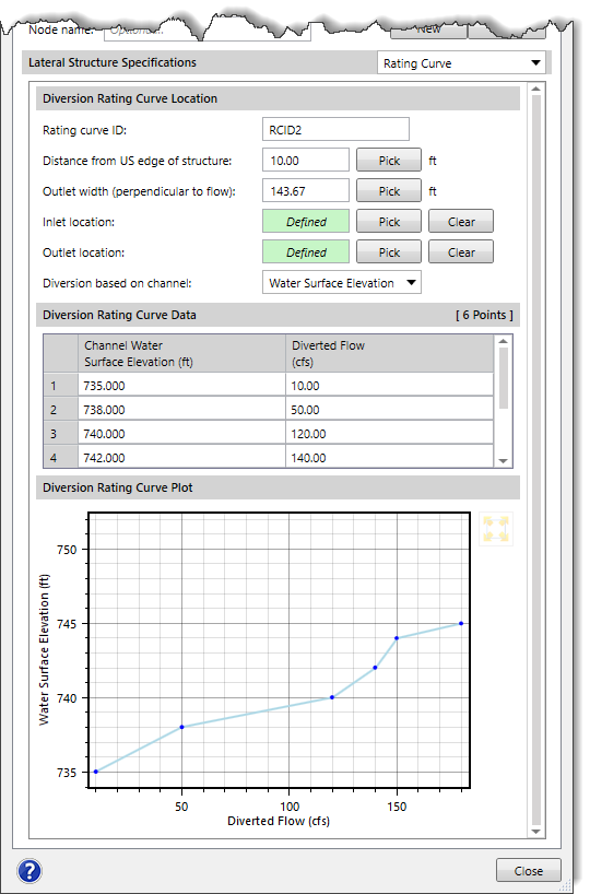
Diversion Rating Curve Location
This section is used to define general information for the rating curve computations.
This section requires the following data:
- Rating curve ID
This entry field is used to assign an ID to the rating curve.
- Distance from US edge of structure
This entry field is used to specify the distance of the lateral structure diversion from the upstream edge of the structure. Alternatively, the user can click the [Pick] button to select the horizontal station from the lateral structure weir on the Map View.
- Outlet width (perpendicular to flow)
This entry field is used to define the outlet width from connection weir perpendicular to the flow direction. Alternatively, the user can click the [Pick] button to measure the outlet width from the connection weir on the Map View.
- Inlet location
This read-only field allows the user to select the inlet location where the water is coming from. The user can click the [Pick] button to select the inlet location upstream of the weir from the Map View. The [Clear] button deletes the selected inlet location.
- Outlet location
This read-only field allows the user to select the outlet location where the water exits. The user can click the [Pick] button to select the outlet location downstream of the weir from the Map View. The [Clear] button deletes the selected outlet location.
- Diversion based on channel
This dropdown combo box allows the user to select the computation type for the rating curve. The following options are available:
- Water Surface Elevation
- Flow
Note that based on the option selected in the Diversion based on channel dropdown combo box, the table contained in a Diversion Rating Curve Data section will be changed.
Diversion Rating Curve Data
This section contains a table for entering and editing lateral structure diversion rating curve data.
- Channel Water Surface Elevation
This column of the table defines the water surface elevation in the main channel for the diversion rating curve. Note that this data column is provided when the Water Surface Elevation rating curve option is selected in the Diversion based on channel dropdown combo box.
- Channel Flow
This column of the table defines the flow in the main channel for the diversion rating curve. Note that this data column is provided when the Flow rating curve option is selected in the Diversion based on channel dropdown combo box.
- Diverted Flow
This column of the table defines the corresponding diverted flow through the lateral structure for the diversion rating curve.
Diversion Rating Curve Plot
This section automatically plots the user-defined diversion rating curve. This visual representation allows the user to assess the behavior of the curve and make adjustments if necessary.
Outlet Time Series Panel
This panel allows the user to specify a name for an outlet time series. Then a flow hydrograph can be specified for the lateral structure in the Unsteady Flow Data command. The flow time series will be labeled in the output based on the user-entered name for the outlet time series. Refer to this article in our knowledge base to learn how to use the Unsteady Flow Data command.
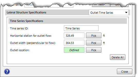
Time Series Specifications
This section requires the following data:
- Time series ID
This entry field is used to assign an ID to the outlet time series.
- Horizontal station for outlet flow
This entry field is used to select the horizontal station for an outlet discharge location on weir geometry. Alternatively, the user can click the [Pick] button to interactively select an outlet discharge location from the Map View.
- Outlet width (perpendicular to flow)
This entry field is used to enter the outlet width from the connection weir. Alternatively, the user can click the [Pick] button to interactively measure the outlet width from the Map View.
- Outlet location
The user can click the [Pick] button to select the outlet location downstream of the weir geometry from the Map View.
The [Delete All] button is used to clear all the data specified within this section.
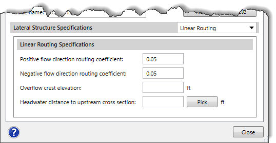
Linear Routing Panel
This panel provides linear routing specifications for the selected lateral structure. The user can choose this panel instead of entering structure information and having the software compute the flow from the structures. Note that this panel is only available when a Linear Routing is selected in the Structure type dropdown combo box of the Lateral Structure Connection Details section under the Connection Data panel. Otherwise, it is disabled (i.e., grayed out).
This panel requires the following data:
- Positive flow direction routing coefficient
This entry field is used to define the linear routing coefficient for positive flow direction (in the defined flow direction of the lateral structure i.e., from headwater to tailwater). The user can enter a coefficient ranging from 0.0 and 1.0, with 1.0 representing routing the maximum flow over the lateral structure and 0.0 representing no flow routed over the lateral structure.
- Negative flow direction routing coefficient
This entry field is used to define the linear routing coefficient for the negative flow direction (opposite the defined flow direction of the lateral structure i.e., from tailwater to headwater). The user can enter a coefficient ranging from 0.0 and 1.0, with 1.0 representing routing the maximum flow over the lateral structure and 0.0 representing no flow routed over the lateral structure.
- Overflow crest elevation
This entry field is used to define the minimum elevation for flow to transfer from one side of the lateral structure to the other. If both water surface elevations are below this crest elevation, then no flow is transferred through the lateral structure.
- Headwater distance to upstream cross section
This entry field is used to define the distance from the lateral structure linear routing diversion and the cross section immediately upstream of the structure on the current river reach. Alternatively, the user can click the [Pick] button to interactively measure this distance from the Map View.
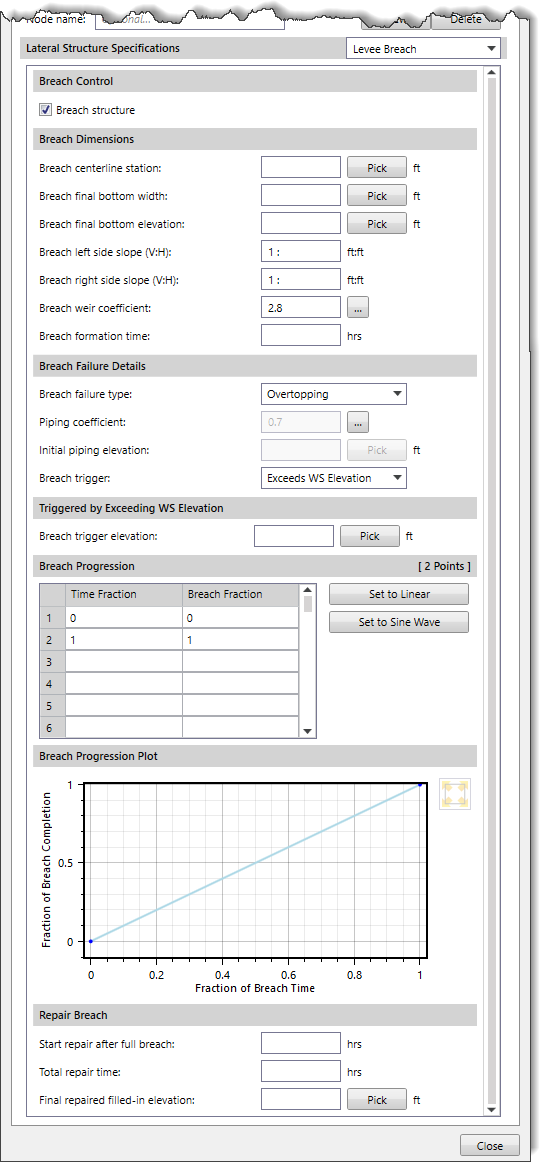
Levee Breach Panel
This panel is used to enter levee breach data for evaluating the breaching of a selected lateral structure. A levee breach in a lateral structure refers to a situation where there is a failure or breach in a levee along a lateral channel or waterway. The levee breach data is only used for unsteady flow models and is ignored in steady flow models. Refer to this article in our knowledge base to learn how to define levee breach data using the Levee Breach panel.
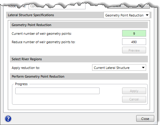
Geometry Point Reduction Panel
This panel is used to automatically filter out unnecessary station elevation points for the lateral structure. Refer to this article in our knowledge base to learn how to define geometry point reduction using the Geometry Point Reduction panel.
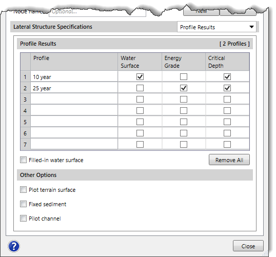
Profile Results Panel
This panel is used to select the analysis results on the lateral structure plot. The table displayed under the Profile Results section lists all of the analyzed water surface profiles for the steady state and maximum water surface for the unsteady state. This allows the user to specify for which profiles the results should be displayed on the lateral structure plot. Refer to this article in our knowledge base to learn how to define profile results using the Profile Results panel.