
Welcome to CivilGEO Knowledge Base
Welcome to CivilGEO Knowledge Base
Storage areas can be defined by drawing the boundary of the area using the Draw Storage Areas command, or by assigning an already drawn polyline or polygon as the boundary using the Assign Storage Areas command. Refer to this article in our knowledge base on how to create a storage area.
Once a storage area has been defined, the user can enter data to describe the storage area. In GeoHECRAS, the Storage Area Data command can be used to view or modify the storage area data. This data includes the area of storage, the minimum elevation, and the elevation-versus-volume relationship. The elevation-versus-volume relationship is a curve that shows how the volume of the storage area changes as the elevation of the water surface changes.
Storage areas can be connected to other storage areas, cross sections, or lateral structures. When a storage area is connected to another storage area, the flow between the two areas is calculated using the storage area’s elevation-versus-volume relationship. When a storage area is connected to a cross section or lateral structure, the flow between the storage area and the cross section or lateral structure is calculated using the cross section’s or lateral structure’s hydraulic parameters.
Storage areas can be used to model a variety of hydrologic processes, including flood routing, water quality, and sediment transport. By using storage areas, GeoHECRAS can be used to simulate the effects of these processes on a river system.
This article describes how to use the Storage Area Data command in GeoHECRAS software.
Follow the steps below to view or modify the storage area data:


The following sections describe how to use the Storage Area Data command and interact with the above dialog box.
The Select Storage Area section allows the user to select the storage area in order to define the storage area data. The user can create a new storage area, copy existing storage area data to a new storage area, and delete a storage area. In addition, the user can navigate between storage areas and enter a description detailing the current storage area.
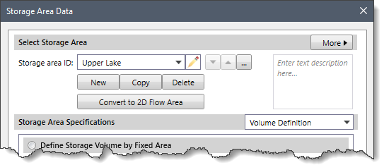
The following options are provided in this section:
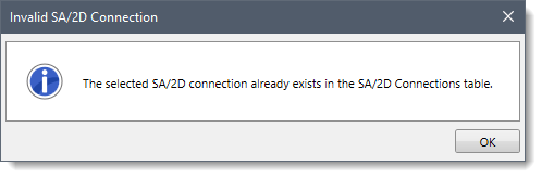
![[Convert to 2D Flow Area] button - Confirm dialog box](/wp-content/uploads/sites/25/2023/12/HEC-RAS-Storage-Area-Data-Command-Image-4.png) Click the [Yes] button and the selected storage area will be converted to a 2D flow area. To abort the process, click the [No] button.
Click the [Yes] button and the selected storage area will be converted to a 2D flow area. To abort the process, click the [No] button.The Storage Area Specifications dropdown combo box contains several data panel entries that allow the user to define storage area data. The following data panel entries are listed in the dropdown combo box:
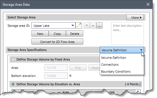
This panel provides different ways of defining the storage area volume. By default, the Volume Definition panel is selected when the Storage Area Data dialog box is displayed.
The following sections describe the Volume Definition data panel:
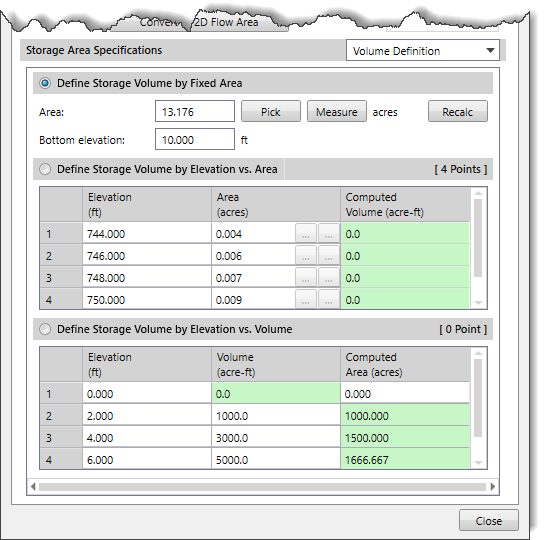
The Define Storage Volume by Fixed Area radio button section allows the volume of the storage area to be defined with a fixed area and a bottom (minimum) elevation. By default, this radio button section is selected.
Note: The storage area is assumed to have the same area at all elevations, therefore the volume is simply the depth times the area.
The following options are provided:
The Define Storage Volume by Elevation vs. Area radio button section allows the volume of the storage area to be defined by a table of elevations and corresponding areas. Select the Define Storage Volume by Elevation vs. Area radio button to enable this section.

The following data columns are provided:
The right-click context menu of the table displays commands to cut, copy, and paste cells, as well as insert and delete rows to and from the table. In addition, the user can copy the table data to the clipboard or export it as a Microsoft Excel or PDF document.

The Define Storage Volume by Elevation vs. Volume radio button section allows the volume of the storage area to be defined by a table of elevations and corresponding accumulated volumes. Select the Define Storage Volume by Elevation vs. Volume radio button to enable this section.

The following data columns are provided:
This data panel displays the connections to and from the current storage area. It provides a central location that lists all of the connections with the current storage area.
 The following sections describe the Connections data panel:
This section provides a table listing all of the SA/2D connections linked to the current storage area.
The following data columns are provided:
 In addition, a [Define] button is provided that allows the user to jump to where the SA/2D connection is defined. Clicking on the [Define] button closes the Storage Area Data dialog box and displays the SA/2D Connections Data dialog box, providing detailed information about the selected SA/2D connection. Refer to this article in our knowledge base to learn more about the SA/2D Connections Data dialog box.
This section provides a table listing the river reaches connected to the current storage area.
The following data columns are provided:
 In addition, a [Define] button is provided that allows the user to jump to where the cross section is defined. Clicking on the [Define] button closes the Storage Area Data dialog box and displays the Cross Section Data dialog box, providing detailed information about the selected cross section. Refer to this article in our knowledge base to learn more about the Cross Section Data dialog box.
This section provides a table listing the lateral structures connected to the current storage area.
The following data columns are provided:
 In addition, a [Define] button is provided that allows the user to jump to where the lateral structure is defined. Clicking on the [Define] button closes the Storage Area Data dialog box and displays the Lateral Structure Data dialog box, providing detailed information about the selected lateral structure. Refer to this article in our knowledge base to learn more about the Lateral Structure Data dialog box.
This panel provides a table listing all of the boundary condition lines linked to the current storage area.
 The following data columns are provided:
In addition, a [Define] button is provided that allows the user to jump to where the boundary condition line is defined. Clicking on the [Define] button closes the Storage Area Data dialog box and displays the Unsteady Flow Data dialog box, providing detailed information about the selected boundary conditions. Refer to this article in our knowledge base to learn more about the Unsteady Flow Data dialog box.


CivilGEO G2 Reviews
4.8/5.0 Rating, Over 230 Reviews

GeoHECRAS is recognized as the top Civil Engineering Design Software with an average of 4.8 out of 5.0 rating from over 230 real user reviews on G2.


We use cookies to give you the best online experience. By agreeing you accept the use of cookies in accordance with our cookie policy.
When you visit any web site, it may store or retrieve information on your browser, mostly in the form of cookies. Control your personal Cookie Services here.


