
Welcome to CivilGEO Knowledge Base
Welcome to CivilGEO Knowledge Base
A culvert is a relatively short segment of conduit that is typically used to transport water underneath a roadway or other type of earthen embankment. Common culvert shapes include circular pipes, rectangular boxes, ellipses, and arches. Noncircular culverts are generally described by their size in terms of a culvert rise and culvert span. The size of a circular culvert is usually expressed in terms of the culvert diameter. There is a wide variety of entrance conditions found at culverts, including square edge, angled wingwalls, beveled edges, entrance mitered to slope, etc.
According to research sponsored by the Federal Highway Administration (FHWA), culvert operation is governed at all times by one of two conditions: inlet control or outlet control (Normann, et al, 1985).
Inlet control is a common governing situation for culvert design, characterized by the fact that the tailwater or culvert barrel conditions allow more flow to be passed through the culvert than the inlet can accept. The inlet itself acts as a controlling or governing section of the culvert, restricting the passage of water into the main barrel.
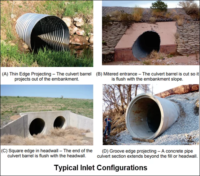 Image Source: https://rashms.com/blog/culvert-analysis-in-hy8-hec-ras-xpswmm/
Outlet control is different from inlet control in that the barrel or tailwater cannot accept as high a flow as the inlet may allow. This may occur with a high tailwater or a long culvert with a rough interior.
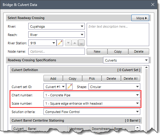
The FHWA Chart Number and Scale Number refer to a series of nomographs published by the Bureau of Public Roads (BPR) (now called the FHWA) 1965. These nomographs allowed the inlet control headwater to be computed for different types of culverts operating under a wide range of flow conditions.
The table displayed below in the article is the Chart Number and Scale Number information from the 1985 FHWA publication. Each of the FHWA charts has two to four separate scales representing different culvert entrance designs. The appropriate FHWA Chart Number and Scale Number should be chosen according to the type of culvert and culvert entrance.
For example, Chart Numbers 1, 2, and 3 apply only to pipe culverts. Similarly, Chart Numbers 8, 9, 10, 11, 12, and 13 apply only to box culverts. The GeoHECRAS software checks the Chart Number to ensure that it is appropriate for the type of culvert being analyzed. GeoHECRAS also checks the value of the Scale Number to ensure that it is available for the given Chart Number. For example, a Scale Number of 4 would be available for chart 11, but not for chart 12.
| Chart Number | Scale Number | Description |
|---|---|---|
| 1 | Concrete Pipe Culvert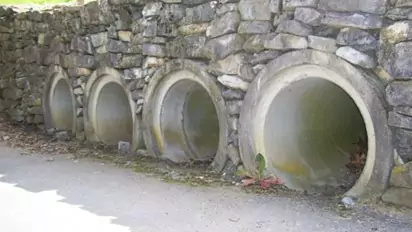 Image Source: https://www.istockphoto.com/photo/row-of-culverts-surrounded-by-a-rock-wall-gm482566842-70135823 |
|
| 1 | Square edge entrance with headwall | |
| 2 | Groove end entrance with headwall | |
| 3 | Groove end entrance, pipe projecting from fill | |
| 2 | Corrugated Metal Pipe Culvert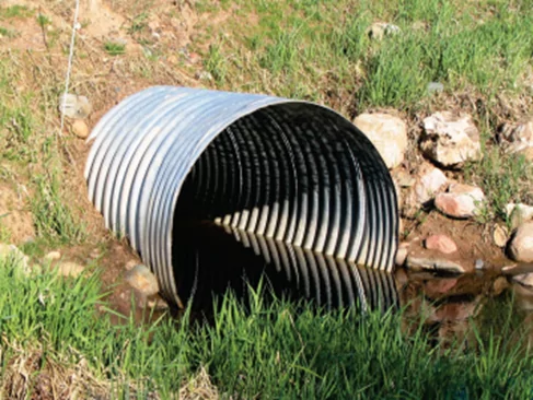 Image Source: https://www.dot.ny.gov/divisions/engineering/structures/repository/events-news/2019_LBC_session_3-1.pdf |
|
| 1 | Headwall | |
| 2 | Mitered to conform to slope | |
| 3 | Pipe projecting from fill | |
| 3 | Concrete Pipe Culvert; Beveled Ring Entrance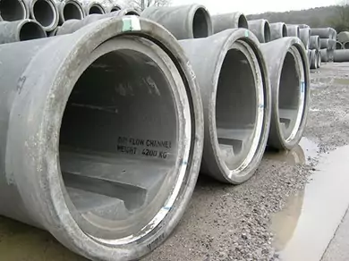 Image Source: https://www.archiexpo.com/prod/cpm-group-ltd/product-69767-2213835.html 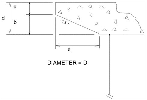 |
|
| 1(A) | Small bevel: b/D = 0.042; a/D = 0.063; c/D = 0.042; d/D = 0.083 | |
| 2(B) | Large bevel; b/D = 0.083; a/D = 0.125; c/D = 0.042; d/D = 0.125 | |
| 8 | Box Culvert with Flared Wingwalls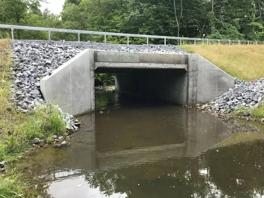 Image Source: https://cmellp.com/portfolio-items/cr57-goode-st-over-mourning-kill-culvert-replacement/#iLightbox[4b532bca7938423d937]/0 |
|
| 1 | Wingwalls flared 30 to 75 degrees | |
| 2 | Wingwalls flared 90 or 15 degrees | |
| 3 | Wingwalls flared 0 degrees (sides extended straight) | |
| 9 | Box Culvert with Flared Wingwalls and Inlet Top Edge Bevel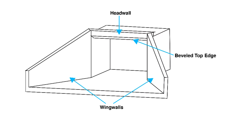 |
|
| 1 | Wingwall flared 45 degrees; inlet top edge bevel = 0.043D | |
| 2 | Wingwall flared 18 to 33.7 degrees; inlet top edge bevel = 0.083D | |
| 10 | Box Culvert; 90-degree Headwall; Chamfered or Beveled Inlet Edges | |
| 1 | Inlet edges chamfered 3/4-inch | |
| 2 | Inlet edges beveled 2-in/ft at 45 degrees (1:1) | |
| 3 | Inlet edges beveled 1-in/ft at 33.7 degrees (1:1.5) | |
| 11 | Box Culvert; Skewed Headwall; Chamfered or Beveled Inlet Edges | |
| 1 | Headwall skewed 45 degrees; inlet edges chamfered 3/4-inch | |
| 2 | Headwall skewed 30 degrees; inlet edges chamfered 3/4-inch | |
| 3 | Headwall skewed 15 degrees; inlet edges chamfered 3/4-inch | |
| 4 | Headwall skewed 10 to 45 degrees; inlet edges beveled | |
| 12 | Box Culvert; Non-Offset Flared Wingwalls; 3/4-inch Chamfer at Top of Inlet | |
| 1 | Wingwalls flared 45 degrees (1:1); inlet not skewed | |
| 2 | Wingwalls flared 18.4 degrees (3:1); inlet not skewed | |
| 3 | Wingwalls flared 18.4 degrees (3:1); inlet skewed 30 degrees | |
| 13 | Box Culvert; Offset Flared Wingwalls; Beveled Edge at Top of Inlet | |
| 1 | Wingwalls flared 45 degrees (1:1); inlet top edge bevel = 0.042D | |
| 2 | Wingwalls flared 33.7 degrees (1.5:1); inlet top edge bevel = 0.083D | |
| 3 | Wingwalls flared 18.4 degrees (3:1); inlet top edge bevel = 0.083D | |
| 16-19 | Corrugated Metal Box Culvert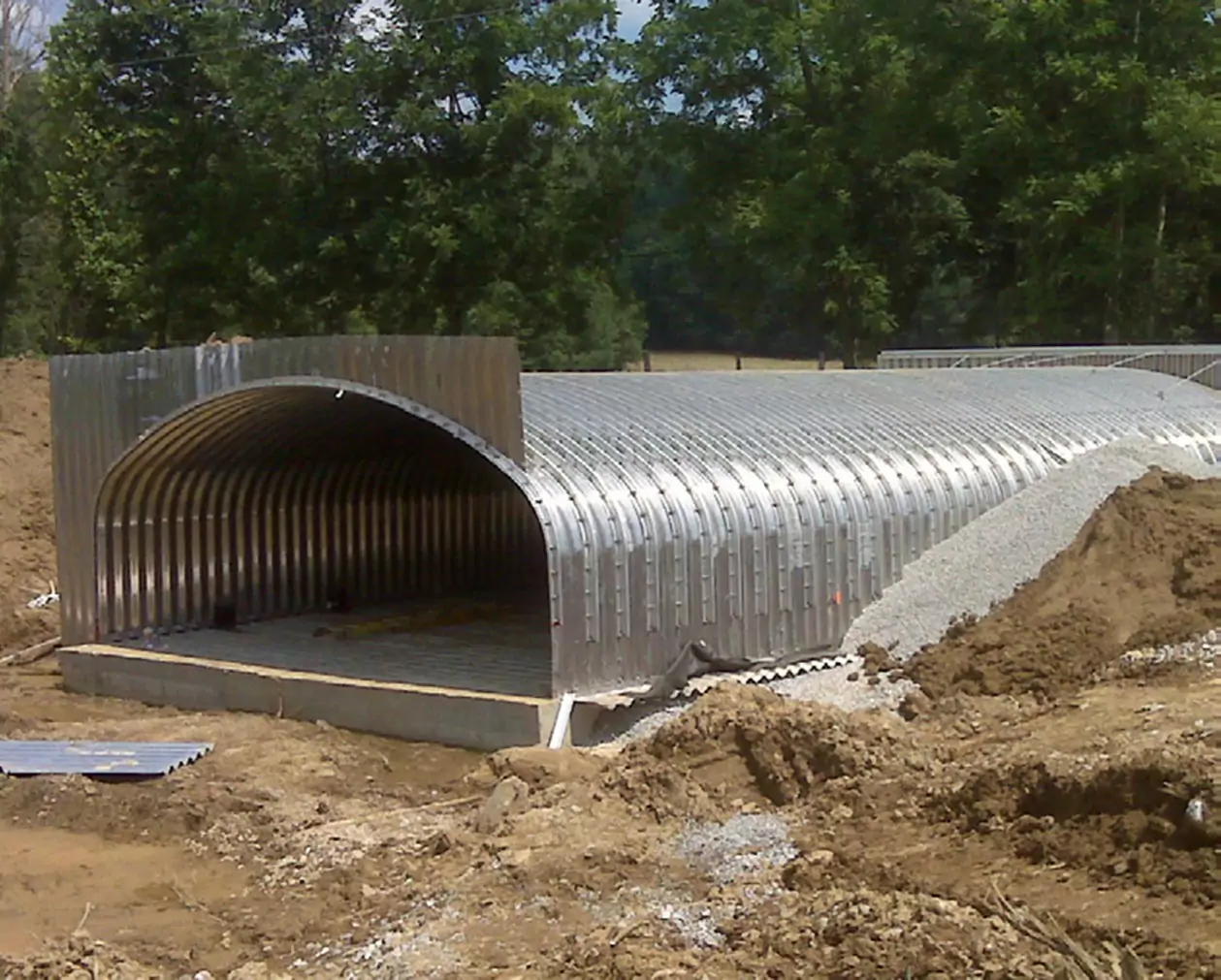 Image Source: https://www.conteches.com/knowledge-center/case-studies/details/slug/ky-2766-culvert-replacement |
|
| 1 | 90-degree headwall | |
| 2 | Thick wall Projecting | |
| 3 | Thin wall projecting | |
| 29 | Horizontal Ellipse; Concrete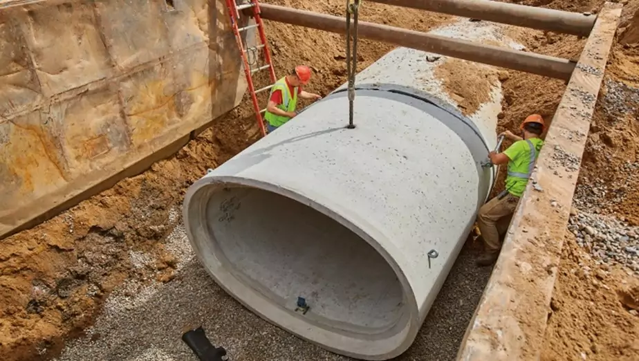 Image Source: https://www.countymaterials.com/en/news/item/projects-with-depth-restrictions-rely-on-elliptical-reinforced-concrete-pipe |
|
| 1 | Square edge with headwall | |
| 2 | Grooved end with headwall | |
| 3 | Grooved end projecting | |
| 30 | Vertical Ellipse; Concrete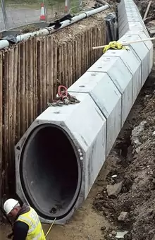 Image Source: https://docplayer.net/91824420-Precast-concrete-solutions.html |
|
| 1 | Square edge with headwall | |
| 2 | Grooved end with headwall | |
| 3 | Grooved end projecting | |
| 34 | Pipe Arch; 18" Corner Radius; Corrugated Metal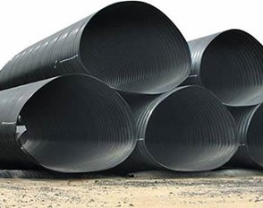 Image Source: https://www.ecplaza.net/products/corrugated-metal-culvert-pipe-arch-3825616 |
|
| 1 | 90 Degree headwall | |
| 2 | Mitered to slope | |
| 3 | Projecting | |
| 35 | Pipe Arch; 18" Corner Radius; Corrugated Metal | |
| 1 | Projecting | |
| 2 | No bevels | |
| 3 | 33.7-degree bevels | |
| 36 | Pipe Arch; 31" Corner Radius; Corrugated Metal | |
| 1 | Projecting | |
| 2 | No bevels | |
| 3 | 33.7-degree bevels | |
| 41-43 | Arch; low-profile arch; high-profile arch; semi-circle; Corrugated Metal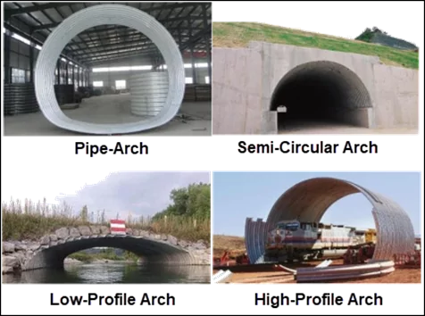 Image Source: https://www.sciencedirect.com/science/article/abs/pii/S0263823122009740 |
|
| 1 | 90-degree headwall | |
| 2 | Mitered to slope | |
| 3 | Thin wall projecting | |
| 55 | Circular Culvert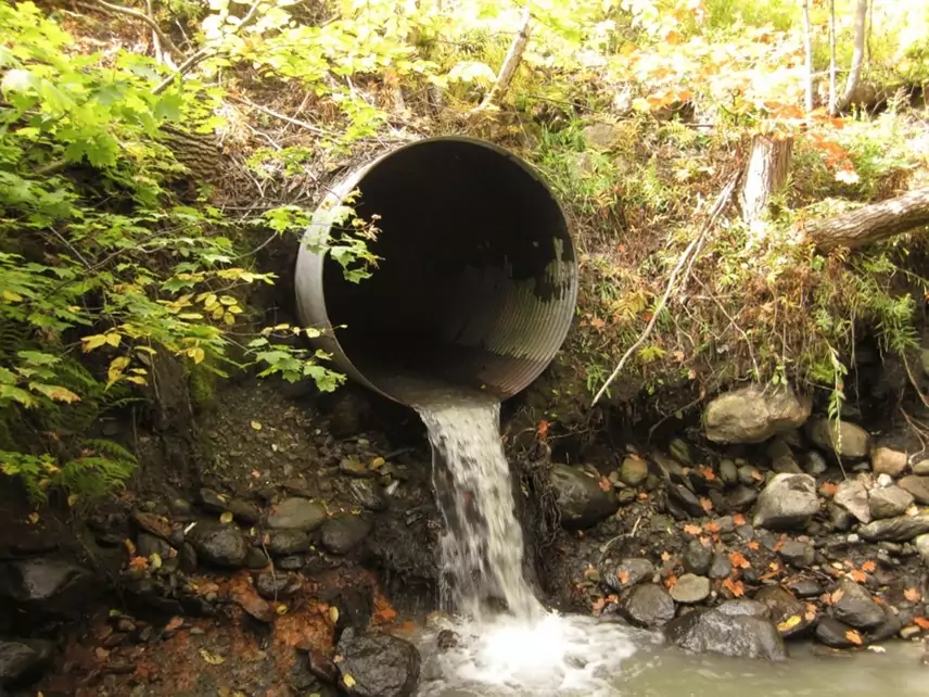 Image Source: https://upload.wikimedia.org/wikipedia/commons/3/38/Culvert_with_a_drop.jpg |
|
| 1 | Smooth tapered inlet throat | |
| 2 | Rough tapered inlet throat | |
| 56 | Elliptical Inlet Face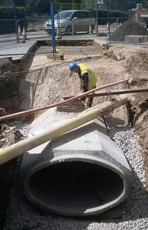 Image Source: https://www.specifiedby.com/stanton-bonna-concrete/box-culverts-alternative |
|
| 1 | Tapered inlet; Beveled edges | |
| 2 | Tapered inlet; Square edges | |
| 3 | Tapered inlet; Thin edge projecting | |
| 57 | Rectangular | |
| 1 | Tapered inlet throat | |
| 58 | Rectangular Concrete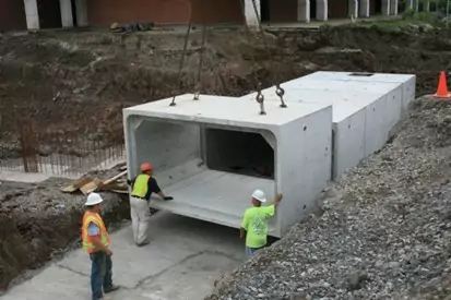 Image Source: https://www.kistner.com/product/box-culvert-specification/ |
|
| 1 | Side tapered; Less favorable edges | |
| 2 | Side tapered; More favorable edges | |
| 59 | Rectangular Concrete | |
| 1 | Slope tapered; Less favorable edges | |
| 2 | Slope tapered; More favorable edges | |
| 60 | ConSpan Span/Rise Approximately 2:1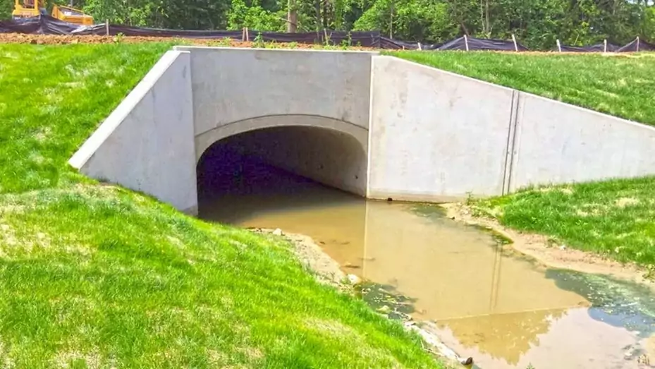 Image Source: https://www.conteches.com/bridges-structures/precast/con-span-i-series |
|
| 1 | 0-degree wingwall angle | |
| 2 | 45-degree wingwall angle | |
| 3 | 90-degree wingwall angle | |
| 61 | ConSpan Span/Rise Approximately 4:1 | |
| 1 | 0-degree wingwall angle | |
| 2 | 45-degree wingwall angle | |
| 3 | 90-degree wingwall angle |
In GeoHECRAS, the user can select from 1, 2, 3, 55, and 56 Chart Numbers and their corresponding Scale Numbers to define culvert data.
 A successful culvert design depends on accurately predicting the effect that a culvert will have on the surrounding area. Typically, culverts can be expected to cause changes in the water surface elevation upstream. The project modeler must estimate these effects to ensure that the change to water elevation upstream headwater will not adversely affect the surrounding community.


CivilGEO G2 Reviews
4.8/5.0 Rating, Over 230 Reviews

GeoHECRAS is recognized as the top Civil Engineering Design Software with an average of 4.8 out of 5.0 rating from over 230 real user reviews on G2.


We use cookies to give you the best online experience. By agreeing you accept the use of cookies in accordance with our cookie policy.
When you visit any web site, it may store or retrieve information on your browser, mostly in the form of cookies. Control your personal Cookie Services here.


