
Welcome to CivilGEO Knowledge Base
Welcome to CivilGEO Knowledge Base
In HEC-RAS, lateral structures are used to model flow being transferred between a river and adjacent elements, such as another river, storage area, or 2D flow area. The lateral structure acts as an internal boundary element between the above model elements, and can represent a levee or flood wall, a flow diversion structure, or the natural terrain. To learn more about lateral structures, refer to this article in our knowledge base.
In GeoHECRAS, the user can draw lateral structures interactively on the map view or assign the already imported GIS shapefiles as a lateral structure.
To create a lateral structure, either the Draw Lateral Structures or Assign Lateral Structures command can be used. Both commands work similarly.
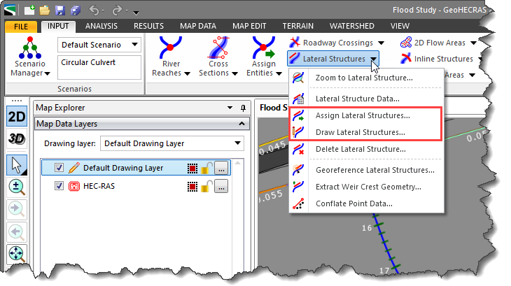
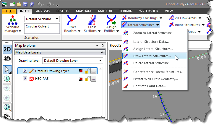
The Draw Lateral Structures command allows the user to interactively draw the centerline of the lateral structure on the Map View. The software will extract the lateral structure geometry from the underlying terrain model.
Follow the steps below to use the Draw Lateral Structures command:
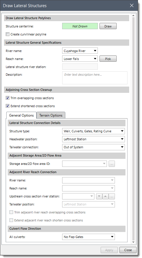 The following sections describe how to use the Draw Lateral Structures command and how to interact with the above dialog box.
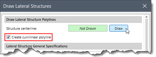
This section is used to draw the lateral structures on the Map View using polylines. To draw a lateral structure polyline, follow the steps below:
This section is used to specify the river, reach and corresponding river station along which the lateral structure is drawn.
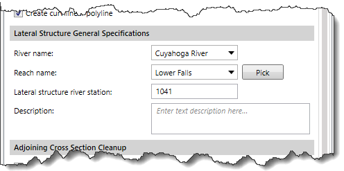
To specify the river and reach, select the river and reach name from the River name and Reach name dropdown combo boxes, respectively. Alternatively, the user can select a reach by clicking on the [Pick] button from the Map View. The user can use the Description box to describe the location of the lateral structures more specifically.
Note that the software automatically picks up the value for the Lateral structure river station. This river station ID identifies the upstream end of the lateral structure.
When defining a lateral structure, it is necessary to trim the extended cross sections and extend the shortened cross sections.
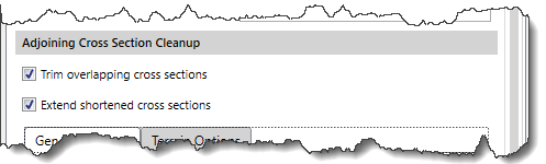
The user should make sure both the Trim overlapping cross sections and Extend shortened cross sections checkboxes are checked by default. This allows the software to automatically trim the extended cross sections and extend the shortened cross section. To learn more about trimming and extending cross sections, refer to this article in our knowledge base.
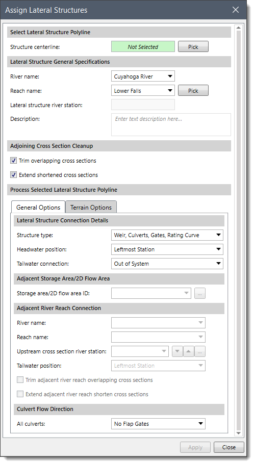
This tabbed panel is used to specify the details of lateral structure connections and identify adjacent model elements.
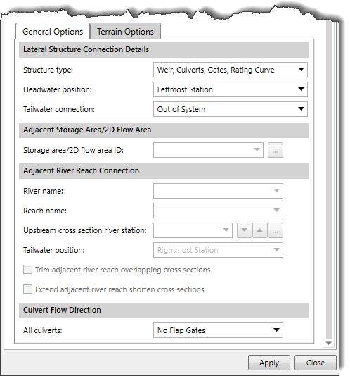
This section is used to select the structure type, the headwater position of the lateral structure, and the tailwater connection in order to define what the lateral structure is connected to within the reach.
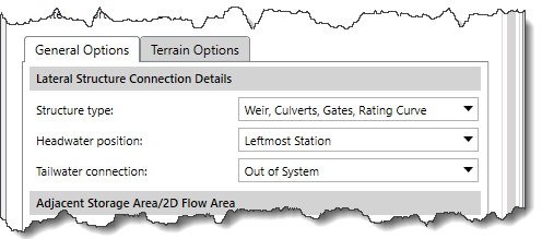
The user can select the type of routing which will be used for lateral structures by using the Structure type dropdown combo box. The Weir, Culverts, Gates, Rating Curve structure type is selected by default, while the Linear Routing selection can be used in the case of multiple lateral structures that are connected to storage areas, but a detailed flow calculation of each lateral structure is not required.
Using the headwater position, the user can determine where the lateral structure is defined spatially within the reach. The user can then specify whether the headwater position is on the right bank, on the rightmost station, on the left bank, or on the leftmost station by selecting it from the Headwater position dropdown combo box.
The lateral structure can be connected to a storage area, 2D flow area, cross sections in another river reach, or nothing at all. To set the tailwater connection, the user can select the connection type from the following options:
When Out of System is selected as the tailwater connection, then no other information is required and hence, both the Adjacent Storage Areas/2D Flow Area and the Adjacent River Reach Connection sections will become inactive.
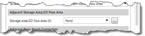
When Adjacent SA/2D Flow Area is selected as the tailwater connection, then the user is required to select the Storage area/2D flow area ID from the dropdown combo box. Alternatively, the user can click […] to go to the Map View and select the required storage area/2D flow area.
When the Adjacent River Reach Connection is selected as the tailwater connection, then the user can select the river, reach, and range of cross sections that connect the lateral structure.
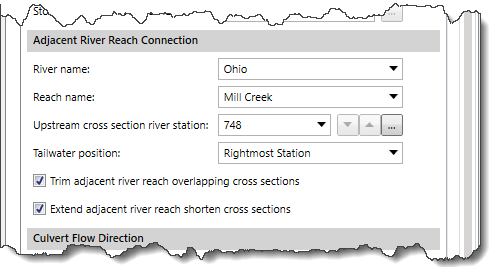
To specify the adjacent river and reach, select the river and reach name from the River name and Reach name dropdown combo boxes, respectively. Then, the user can select the upstream cross section river station using the Upstream cross section river station combo box or by clicking the […] button to pick the station ID from the Map View. This river station ID identifies the tailwater connection of the upstream end of the lateral structure.
The user must specify whether the tailwater position is on the right bank, on the rightmost station, on the left bank, or on the leftmost station by selecting it from the Tailwater position dropdown combo box.
In addition, the user can check the Trim adjacent river reach overlapping cross sections and Extend adjacent river reach shorten cross sections checkboxes to trim the extended cross sections and extend the shortened cross section of the adjacent river.
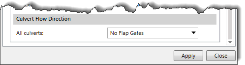
This section determines the direction of the culvert. This option only affects the flow through the culverts, not flow through the weirs or gated structures. The user can select the culvert flow direction from the All culverts combo box.
This tabbed panel is used to define the source elevation data that can be used to extract the weir geometry for the lateral structure defined from the digital terrain layers.
This section defines the primary elevation data of the lateral structure.
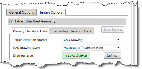
Depending upon the elevation data source type that is selected, different options are provided to specify additional elevation data information. For information on the types of terrain elevation data, refer to this article in our knowledge base.
As secondary elevation data, the user can use an additional elevation data source if it is available in the same project.
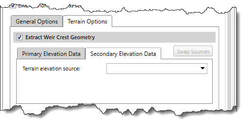
Note that the user can switch elevation data sources by clicking the [Swap Sources] button.
The software will now create a structure on the location where the user drew the centerline, and the cross sections length is adjusted automatically.
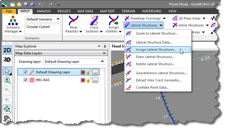
To use the Assign Lateral Structures command, a polyline that can be selected for the purpose of assigning the lateral structure must already exist on the Map View. The software will extract the lateral structure geometry from the underlying terrain model.
Follow the steps below to use the Assign Lateral Structures command:
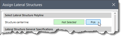
 The following sections describe how to use the Assign Lateral Structures command and how to interact with the above dialog box.
This section describes how to assign a lateral structure polyline while using the Assign Lateral Structures command. Follow the steps below:
The software will now treat the polyline as a lateral structure and adjust the cross sections accordingly.
Note that the remaining sections of the Assign Lateral Structures command are similar to that of the Draw Lateral Structures command. So, the user can refer to these sections explained above in the article.


CivilGEO G2 Reviews
4.8/5.0 Rating, Over 230 Reviews

GeoHECRAS is recognized as the top Civil Engineering Design Software with an average of 4.8 out of 5.0 rating from over 230 real user reviews on G2.


We use cookies to give you the best online experience. By agreeing you accept the use of cookies in accordance with our cookie policy.
When you visit any web site, it may store or retrieve information on your browser, mostly in the form of cookies. Control your personal Cookie Services here.


