
Welcome to CivilGEO Knowledge Base
Welcome to CivilGEO Knowledge Base
In GeoHECRAS, storage areas or 2D flow area connections are used to link two storage areas together with a hydraulic structure or two 2D flow areas, or a storage area to a 2D flow area. The user can draw storage area or 2D flow area connections interactively on the map view or assign the already imported GIS shapefiles as a storage area or 2D flow area connection. The software allows the user to place a hydraulic structure in the middle of a 2D flow area to control how flow travels from one series of cells to another series of cells. Storage area or 2D flow area connections can consist of a weir and gated spillway, culverts, bridge, just a weir, or linear routing option.
To establish a hydraulic connection between two storage areas, 2D flow areas, or inside a 2D flow area, the Draw SA/2D Connections or Assign SA/2D Connections command can be used. Both commands work similarly.
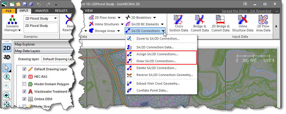
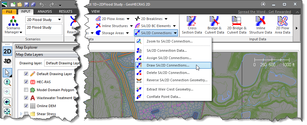
The Draw SA/2D Connections command allows the user to interactively draw the centerline of the storage area or 2D flow area connections on the Map View.
Follow the steps below to use the Draw SA/2D Connections command:
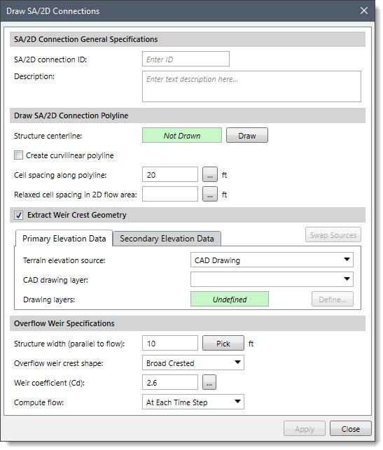
The following sections describe how to draw SA/2D connections and interact with the above dialog box.
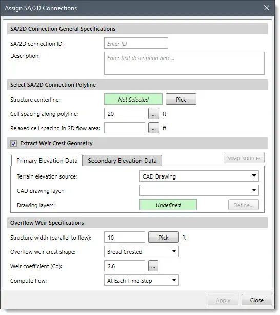
This section is used to specify the storage area or 2D flow area connection ID. The SA/2D connection ID field is used to enter the storage area or 2D flow area connection ID to identify each connection location uniquely. The user can use the Description box to describe the location of the storage area or 2D flow area connection in more detail.
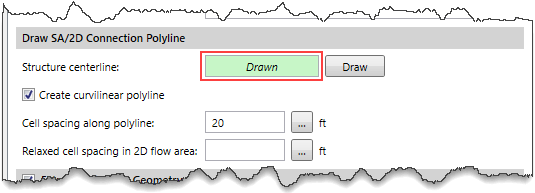
The Draw SA/2D Connection Polyline section is used to draw the storage area or 2D flow area connection centerline on the Map View using polylines.
To draw a SA/2D connection polyline, follow the steps below:
![[Draw] button](/wp-content/uploads/sites/25/2022/05/Storage-Area-Connection-Image-4.png)
This section allows the user to select the source elevation data for extracting the weir crest geometry. By default, the Extract Weir Crest Geometry section is enabled. If this section is disabled, the software does not extract the weir geometry.
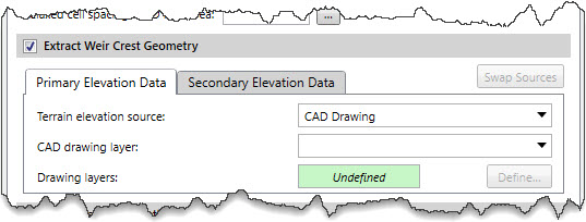
The user can use the Primary and Secondary Elevation Data panels to define the primary and secondary (if available in the project) elevation data sources for extracting the weir crest geometry. Depending upon the elevation data source type that is selected, different options are provided to specify additional elevation data information.
Refer to this article in our knowledge base for information on the types of terrain elevation data that can be used for constructing cross sections.
When a secondary elevation data source is available, the software will form a concave hull around the primary elevation data source to identify its bounds. For locations where elevation data from the primary data source is unavailable, the software will use the elevation data from the secondary data source.
Note that the user cannot utilize the same data source for defining the primary and secondary elevation data.
The user can click the [Swap Sources] button to swap the selected elevation source from primary elevation data to secondary elevation data and vice versa.
The Overflow Weir Specifications section is used to define specifications for the overflow weir.
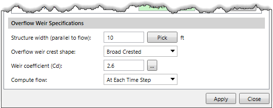
The Structure width (parallel to flow) entry field defines the width of the top of the structure. By default, the software uses a value of 10 ft. Alternatively, the user can click the [Pick] button to measure the structure width from the Map View.
The Overflow weir crest shape dropdown combo box entry allows the user to specify weir types. Two options are available: Broad Crested and Ogee. The user can choose the weir type that best matches the problem.
If the user selects the Ogee shaped weir, two additional parameters: Spillway approach height and Design energy head are displayed in the Overflow Weir Specifications section.
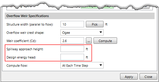
The Spillway approach height entry field is used to define the height which is equal to the elevation of the spillway crest minus the mean elevation of the ground just upstream of the spillway.
The Design energy head entry field is used to define the height which is equal to the energy grade line elevation minus the elevation of the spillway crest.
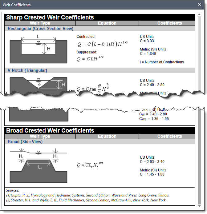
The Weir Coefficient (Cd) entry field allows the user to enter a weir coefficient that will be used in the weir computations. Note that different coefficients are used depending on units such as US Units or Metric (SI) Units. By default, the software uses a value of 2.6. Clicking on the […] button will display a lookup dialog box containing weir coefficients.
Note that if the Ogee shaped weir is selected, the user can compute the weir coefficient based on the approach and design energy head by clicking the [Compute] button.
The Compute flow dropdown combo box entry allows the user to define the computational method, which can be one of the following:
When the data has been defined in the Draw SA/2D Connections dialog box, click the [Apply] button. The software will then create a connection on the location where the user drew the centerline.
The Assign SA/2D Connections command allows the user to manually assign polylines as storage areas or 2D flow area connections. To use this command, a polyline that can be selected must already exist on the Map View to represent the storage area or flow area connection.
Follow the steps below to use the Assign SA/2D Connections command:

![[Pick] button](/wp-content/uploads/sites/25/2022/05/Storage-Area-Connection-Image-12.jpeg)


CivilGEO G2 Reviews
4.8/5.0 Rating, Over 230 Reviews

GeoHECRAS is recognized as the top Civil Engineering Design Software with an average of 4.8 out of 5.0 rating from over 230 real user reviews on G2.


We use cookies to give you the best online experience. By agreeing you accept the use of cookies in accordance with our cookie policy.
When you visit any web site, it may store or retrieve information on your browser, mostly in the form of cookies. Control your personal Cookie Services here.


