
Welcome to CivilGEO Knowledge Base
Welcome to CivilGEO Knowledge Base
The vertices define the geometry of the polyline. Generally, vertex spacing has no strategic importance. However, vertex spacing is important when the polylines are used for automatic mesh generation. In this situation, the vertex spacing defines the mesh density, and each mesh element is defined by a pair of adjacent vertices. The mesh gradation is controlled by the vertex spacing. In areas where a finer mesh is required, the vertices need to be closer together. By contrast, the vertices need to be farther apart in areas where a coarse mesh is required.
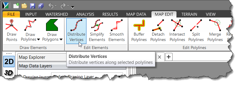
In CivilGEO’s software, the Distribute Vertices command can be used to control the vertex spacing and their distributions to define the polyline geometry.
Follow the steps below to use the Distribute Vertices command:
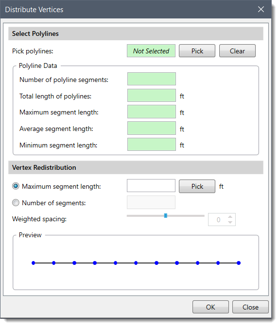
The following sections describe the Distribute Vertices command and how to interact with the above dialog box.
If one or more polylines have been selected before running the Distribute Vertices command, the selected polyline(s) data will be displayed in the dialog box. Alternatively, the user can click the [Pick] button to select the polyline from the Map View. The dialog box will temporarily disappear, and a prompt will be displayed on the status bar instructing the user to select the polyline(s).
Note that the user can also select polyline edges that are arranged in a polygon shape.
After selecting the polyline(s) from the Map View, either right-click and select Done from the context menu or press the [Enter] key to complete the selection. The user will be returned to the dialog box, and the Pick polylines read-only field will display the number of the selected polyline(s).
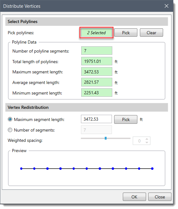
The following Polyline Data will be displayed for the selected polyline(s):
This section is used to control the redistribution of the existing vertices in the polyline(s). The following options are available:
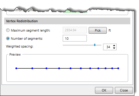
After defining the vertex distribution parameters, click the [OK] button, and the software will redistribute the vertices of the selected polyline(s) as per the user-defined parameters.


CivilGEO G2 Reviews
4.8/5.0 Rating, Over 230 Reviews

GeoHECRAS is recognized as the top Civil Engineering Design Software with an average of 4.8 out of 5.0 rating from over 230 real user reviews on G2.


We use cookies to give you the best online experience. By agreeing you accept the use of cookies in accordance with our cookie policy.
When you visit any web site, it may store or retrieve information on your browser, mostly in the form of cookies. Control your personal Cookie Services here.


