
Welcome to CivilGEO Knowledge Base
Welcome to CivilGEO Knowledge Base
Digitizing (or drawing) elements on the Map View can be performed using various model specific commands (e.g., Draw Storage Areas) or generic draw commands (e.g., Draw Polylines).
When digitizing polylines, polygons, and other model elements, the user is given the option to create curvilinear elements. This option provides a more naturally looking element. The software will fit a cubic spline through the digitized points, as shown below.
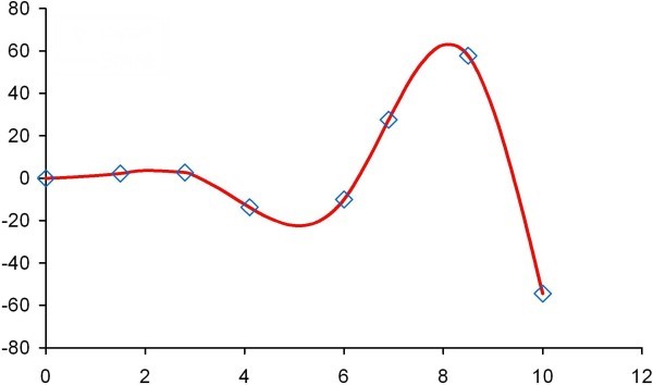
Once the user has completed digitizing the curvilinear element, the software automatically inserts intermediate vertices to represent the curved element using short straight-line polyline segments.
While digitizing using the curvilinear option, additional vertices need to be digitized to transition between straight-line sections and curved sections. These additional vertices anchor the straight-line section and prevent it from becoming curved.
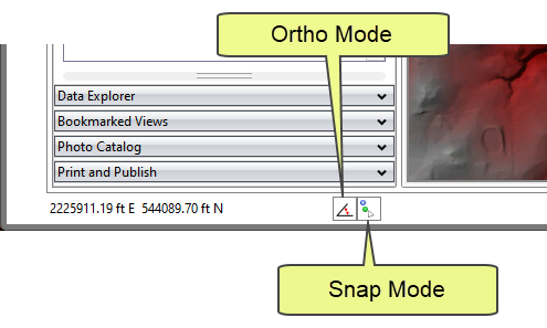
While drawing the curvilinear elements, the user can press and hold the [Shift] key to activate the orthogonal mode and the [Ctrl] key to switch to linear digitizing. This provides more control over the placement of the polylines where additional detail is needed.
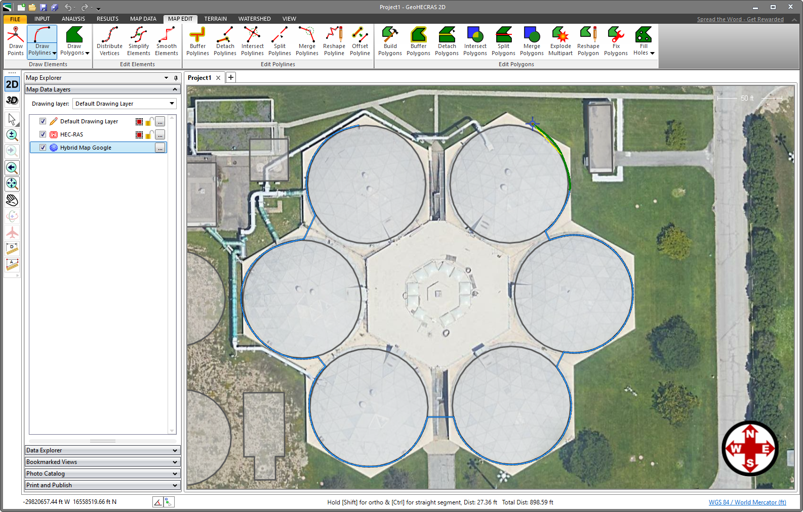
Note that the tooltips for drawing the linear, curvilinear, and orthogonal segments are displayed on the status bar.
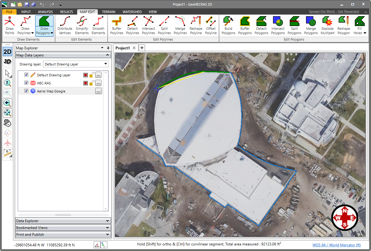
The software, by default, allows the user to draw polygons and other model elements with linear elements. Linear elements are formative design elements used to represent linear features of model elements such as river stretches, roadway crossings, and bridge piers.
While drawing the linear elements, the user can press and hold the [Shift] key to activate the orthogonal mode and [Ctrl] key to switch to curvilinear digitizing.
While the digitizing command is active, press the Esc key to cancel the command. The software will cancel the digitizing command.
While digitizing an element, press the CTRL+Z key (for Undo) to undo the last segment of the element being digitized. The CTRL+Z key can be pressed multiple times to undo multiple segments of the element while digitizing.


CivilGEO G2 Reviews
4.8/5.0 Rating, Over 230 Reviews

GeoHECRAS is recognized as the top Civil Engineering Design Software with an average of 4.8 out of 5.0 rating from over 230 real user reviews on G2.


We use cookies to give you the best online experience. By agreeing you accept the use of cookies in accordance with our cookie policy.
When you visit any web site, it may store or retrieve information on your browser, mostly in the form of cookies. Control your personal Cookie Services here.


