
Welcome to CivilGEO Knowledge Base
Welcome to CivilGEO Knowledge Base
In developing HEC-HMS models, there are essentially two requirements – a runoff-generation component and a routing component. Routing is an essential component of any hydrology modeling project for the derivation of time series of flows into the oceans and studies of climate/land use change on water resources.
While a reach element conceptually represents a segment of stream or river, the actual calculations are performed by a routing method contained within the reach. Several routing methods are defined in GeoHECHMS. Each method implements a hydrologic routing methodology comparable to a hydraulic approach that implements the full unsteady flow equations.
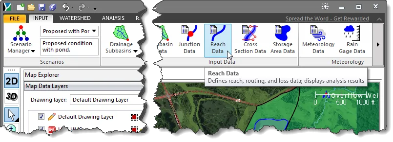
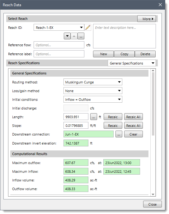
The routing method for a reach can be selected from the Reach Specifications section of the Reach Data dialog box.
Follow the steps given below to select a routing method:
 Alternatively, the user can either double click on the reach polyline from the Map View or choose the Reach Data command from the Routing Reaches dropdown menu of the Input ribbon menu.
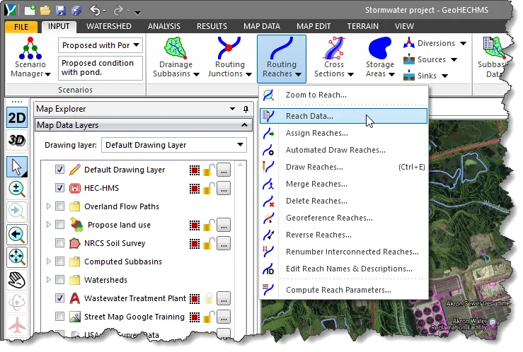
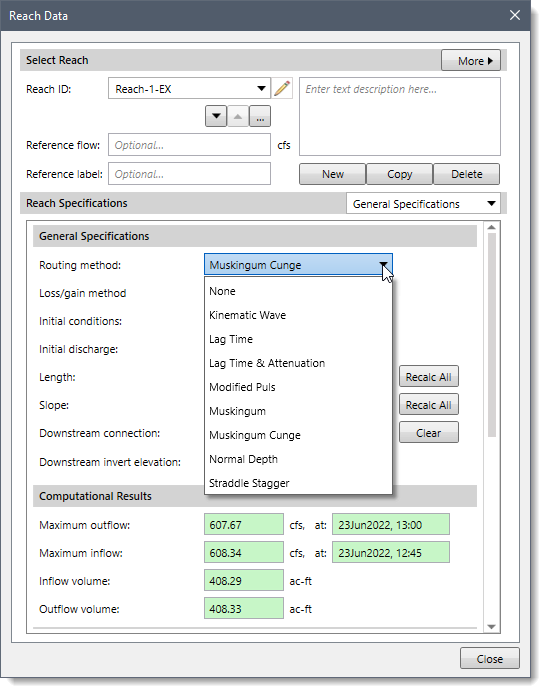
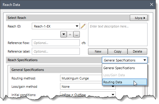
The following sections describe different routing methods and how to define the data for each method in the Routing Data panel.
When None is selected for the Routing method, the Routing Data dropdown combo box entry is disabled (i.e., grayed out).
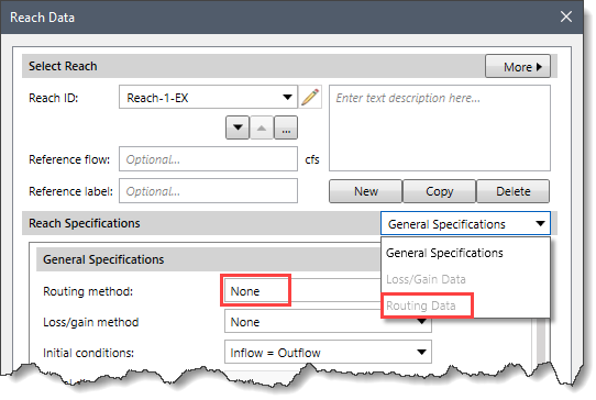
If the user chooses the None method, the reach will translate flow instantaneously and without attenuation.
The Kinematic Wave routing method approximates the full unsteady flow equations by ignoring inertial and pressure forces. It is assumed that the energy slope is equal to the bed slope. Consequently, this method is best suited to fairly steep streams. It is often used in urban areas where natural channels have been modified to have regular shapes and slopes.
When Kinematic Wave is selected for the Routing method, the following data panel will be displayed.
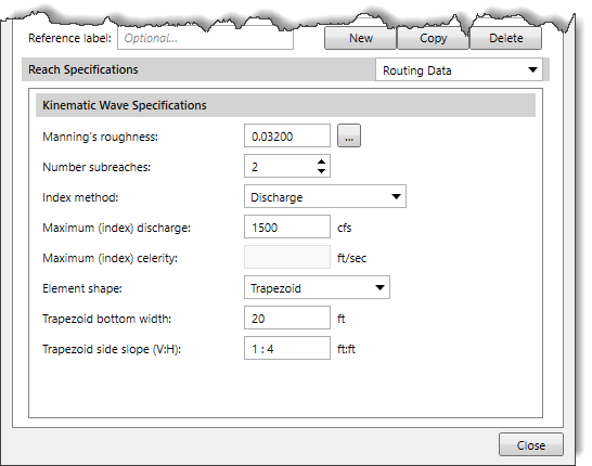
The following input parameters are provided in the data panel:
Note that the Trapezoid bottom width and Trapezoid side slope (V:H) options will be replaced by other parameters according to the shape selected from the Element shape dropdown combo box.
The Lag Time routing method only represents the translation of flood waves. It does not include any representation of attenuation or diffusion processes. Consequently, it is best suited to short stream segments with a predictable travel time that does not vary with flow depth.
When Lag Time is selected for the Routing method, the following data panel is shown.
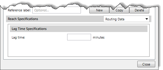
Reach routing lag time is computed based upon the flow velocity in the reach routing element.
Lag time is the amount of time (i.e., travel time) that the inflow hydrograph will be translated as it moves through the reach.
The Lag Time and Attenuation routing method is a hydrologic storage routing method based on a graphical routing technique that is extensively used by the National Weather Service. The method is a special case of the Muskingum method where channel storage is represented by the prism component alone with no wedge storage (i.e., Muskingum X = 0). The lack of wedge storage means that the method should only be used for slowly varying flood waves. Like all hydrologic routing methods, it does not account for complex flow conditions such as backwater effects and/or hydraulic structures.
When Lag Time & Attenuation is selected for the Routing method, the following data panel is shown.
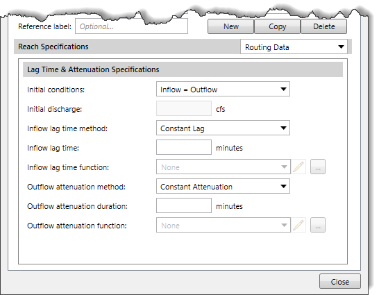
The following input parameters are provided in the data panel.
The Modified Puls routing method is also known as storage routing or level pool routing. It uses conservation of mass and a relationship between storage and discharge to route flow through the stream reach. Attenuation is achieved through the storage and delayed release of water in the reach instead of through a rigorous conservation of momentum approach. It can be useful for representing backwater due to flow constrictions in a channel so long as the backwater effects are fully contained within reach.
When Modified Puls is selected for the Routing method, the following data panel is shown.
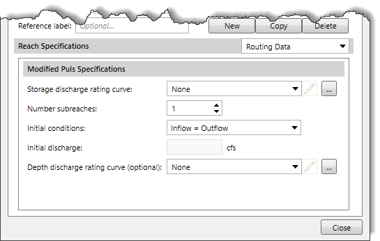
The following input parameters are provided in the data panel.
The Muskingum routing method uses a simple conservation of mass approach to route flow through the stream reach. However, it does not assume that the water surface is level. By assuming a linear, but non-level, water surface it is possible to account for increased storage during the rising side of a flood wave and decreased storage during the falling side. By adding a travel time for the reach and a weighting between the influence of inflow and outflow, it is possible to approximate attenuation.
When Muskingum is selected for the Routing method, the following data panel is shown.
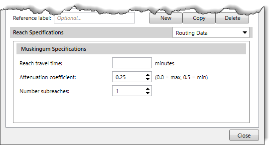
The following input parameters are provided in the data panel.
The Muskingum-Cunge routing method is based on the combination of the conservation of mass and the diffusion representation of the conservation of momentum. It is sometimes referred to as a variable coefficient method because the routing parameters are recalculated every time step based on channel properties and the flow depth. It represents the attenuation of flood waves and can be used in reaches with a small slope.
When Muskingum Cunge is selected for the Routing method, the following data panel is shown.
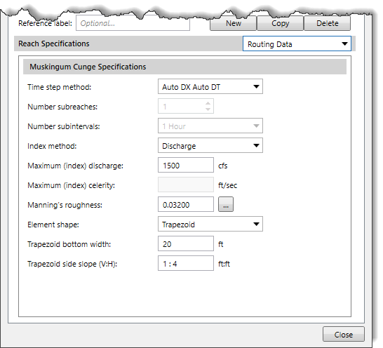
The following input parameters are provided in the data panel.
Note that the Trapezoid bottom width and Trapezoid side slope (V:H) options will be replaced according to the shape selected from the Element shape dropdown combo box.
Based on the selected shape, the interface of the Reach Data dialog box will change. When a user selects 8-Point Cross Section or Tabular Cross Section as an element shape, the Cross Section Geometry section will get enabled. This section is located below the Muskingum Cunge Specifications section.
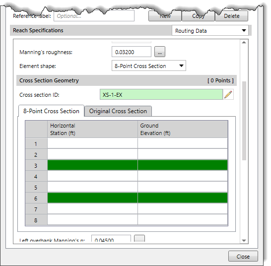
The 8-point shape requires a cross section simplified with only eight station-elevation values. The cross section is usually configured to represent the main channel plus left and right overbank areas. A separate Manning’s n value is entered for each overbank. The cross section should extend from the channel invert up to the maximum water surface elevation that will be encountered during a simulation.
If the tabular shape is used, you will also have to select multiple curves that describe how discharge, area, and top width changes with elevation. These curves must be defined as elevation-discharge, elevation-area, and elevation-width functions, respectively, in the paired data manager before they can be used in the reach element. These curves must be monotonically increasing. Within each of the curves mentioned above, the x-axis defines the elevation, while the y-axis defines the variable of interest. Elevations must be monotonically increasing.
Refer to this article in our knowledge base to know more about 8-Point Cross Section and Tabular Cross Section.
The Normal Depth routing method uses a Modified Puls routing approach where storage-discharge relationships are developed using a normal depth assumption for the reach. The user enters geometric data for the channel. HEC-HMS computes the storage-discharge relationship for the given channel using Manning’s equation for normal depth. HEC-HMS computes the number of Modified Puls subreaches by dividing the travel time by the simulation time interval.
When Normal Depth is selected for the Routing method, the following data panel is shown.
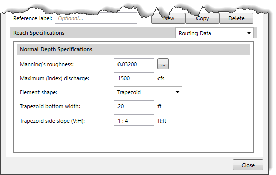
The following input parameters are provided in the data panel.
Note that the Trapezoid bottom width and Trapezoid side slope (V:H) options will change according to the shape selected from the Element shape dropdown combo box.
The Straddle Stagger method uses empirical representations of translation and attenuation processes to route water through a reach. Inflow is delayed a specified amount of time. The delayed flows are averaged over a specified amount of time to produce the final outflow.
When Straddle Stagger is selected for the Routing method, the following data panel is shown.
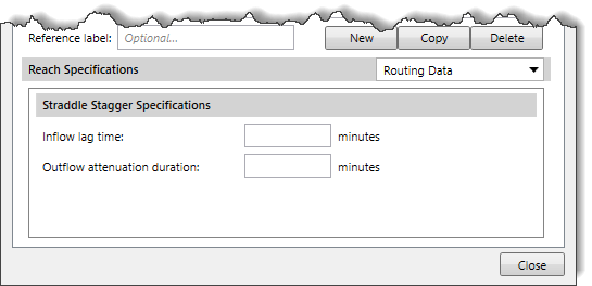
The following input parameters are provided in the data panel.
| Pros | Cons |
|---|---|
| The significant advantage of this method is that it can describe spatial and/or temporal rainfall and roughness variations, which the SCS method, by virtue of it being lumped, cannot do. | It requires an accurate specification of the loss rate as the KWN accounts for direct runoff through the prescription of the effective rain. |
| This method offers the benefits of nonlinear response without needing an unduly complicated or costly solution procedure. | This method cannot account for the influences of backwater on the flood wave because it is based on uniform-flow assumptions. |
| The kinematic wave is suitable for situations where the local and convective acceleration and the pressure term in the dynamic wave model are negligible with respect to the friction and body forces. | This method neglects the diffusive characteristics of flood propagation, resulting in no attenuation occurring in the model, which appears unrealistic. |
| Pros | Cons |
|---|---|
| The main advantage of this method is that it is simple. There is only one parameter to estimate. | It is only accurate in steep streams with little to no available storage. |
| This method is best suited to short stream segments with a predictable travel time that doesn't vary with changing conditions | This method is only appropriate for use in streams that experience no attenuation. |
| It cannot simulate backwater effects or impacts of hydraulic structures. |
| Pros | Cons |
|---|---|
| This technique can be used for time lag with or without any flood peak attenuation. | It is only valid for slowly varying flood waves. |
| It is based on a graphical routing technique that is extensively used by the National Weather Service. | This method does not account for complex flow conditions such as backwater effects and/or hydraulic structures. |
| Pros | Cons |
|---|---|
| This method can simulate backwater effects. | This method should not be used for steep hydrographs. |
| The Modified Puls method can model a reach as a series of cascading, level pools with a user-specified storage-discharge relationship. | Modified Puls technique, in some cases, may not be applicable where reservoirs are operated with controlled outflow. |
| Pros | Cons |
|---|---|
| The main advantage of this method is that it’s simple. Because it’s simple, it has been successfully used all over the world for numerous types of applications. | This method cannot simulate variable translation and attenuation effects. |
| It includes only a few parameters necessary to explain the variation of runoff volume. | This method is only appropriate for use in moderately steep streams (bed slopes > 2 ft/mi). |
| This method is easy to set up and use because only a few parameters are used. | This method cannot simulate backwater effects or impacts of hydraulic structures. |
| Pros | Cons |
|---|---|
| A significant advantage of this method is that the predicted values are in accordance with open channel flow theory. | This method is less parsimonious. |
| The user can simulate variable translation and attenuation effects. | It is only appropriate for use in moderately steep streams (bed slopes > 2 ft/mi). |
| The required parameters can be estimated using physically measurable characteristics of the reach in question. | It cannot simulate backwater effects or impacts of hydraulic structures. |
| Muskingum-Cunge has comparable accuracy to other hydrological routing models such as Modified Puls or Kinematic Wave. |
| Pros | Cons |
|---|---|
| Multiple channel shapes and properties can be used within this method. | This routing method is not applicable when hydrograph data is not available. |
| This method expands upon the Modified Puls method by automatically developing storage vs. discharge relationships. | This routing approach is not appropriate when the flood exits the bank and enters the floodplain. |
| Pros | Cons |
|---|---|
| This method gives best results when applied to slowly fluctuating rivers. | This method does not consider storage. |
| This method is suitable with rivers with little floodplain storage. | This average lag method is purely empirical, being limited to conditions where the inflow-outflow relationship is calibrated using observed values. |


CivilGEO G2 Reviews
4.8/5.0 Rating, Over 230 Reviews

GeoHECRAS is recognized as the top Civil Engineering Design Software with an average of 4.8 out of 5.0 rating from over 230 real user reviews on G2.


We use cookies to give you the best online experience. By agreeing you accept the use of cookies in accordance with our cookie policy.
When you visit any web site, it may store or retrieve information on your browser, mostly in the form of cookies. Control your personal Cookie Services here.


