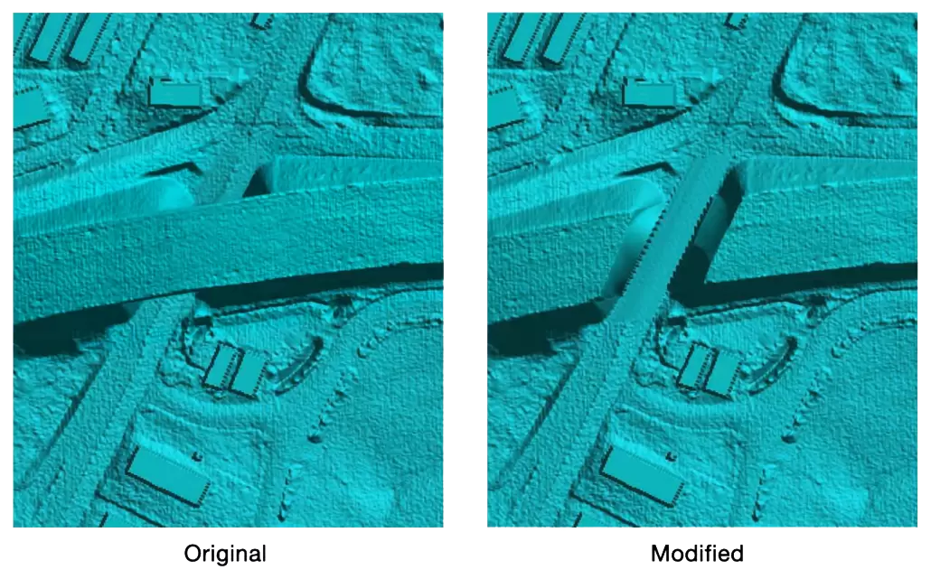
The Stamp Geometry command is used to draw a polyline, prompt the software to automatically sample the cross sectional geometry at the ends of the polyline, linearly interpolate the cross section shape along the drawn polyline, and revise the terrain model accordingly. This can be used to quickly “burn-in” a channel where one is missing, or “fill-in” a levee or dam structure where one is proposed. For example, when performing a laser scan, the bridge deck will cause a false dam to be inserted into the terrain, which will later need to be removed. Users can use the Stamp Geometry command in such a case.
Follow these steps to use the Stamp Geometry command:
- From the Terrain ribbon menu, select the Stamp Geometry command.

- The Stamp Geometry dialog box will be displayed.

The following sections describe how to interact with the above dialog box.
Stamping Parameters
This section is used to define general parameters used for stamping terrain geometry. This includes type of stamping operation to be processed, source terrain surface to be updated, and daylighting method for terrain stamping.
From the Terrain stamping operation dropdown combo box, select the type of stamping operation. The following options are available:
- Terrain Cut: This option cuts the terrain geometry to burn-in a channel where one is missing, or to remove a false dam, etc.
- Terrain Fill: This option fills in a levee or dam structure, where one is proposed, by stamping it on the terrain geometry.

From the Terrain surface dropdown combo box, select the source terrain file. The dropdown combo box will list all the elevation layers that are currently added to the project. The elevation layer which is used to extract cross sections and 2D model elevation data is selected by default.
The Fill void space below terrain cut and the Leave existing ground above terrain checkbox options are checked by default. They facilitate creating a more accurate representation of the stamped terrain geometry by daylighting the stamping operation into the source terrain geometry.
Define Interpolation Path
This section defines the path to which the terrain surface stamping is to be applied. There are two radio button options for defining the path:
- Assign polyline: This option allows the user to select a polyline from the Map View and use it to define the terrain interpolation path.
- Draw polyline: This option allows the user to interactively draw a polyline on the Map View and use it as the terrain interpolation path.
If there is an existing polyline on the Map View that can be used for the stamping operation, the user can click the [Pick] button adjacent to the Assign polyline radio button and select a polyline from the Map View.

Alternatively, the user can click the [Draw] button adjacent to the Draw polyline radio button to draw a polyline on the Map View.
![Click the [Draw] button](https://knowledge.www.civilgeo.com/wp-content/uploads/sites/25/2023/03/Stamp-Geometry-Command-Img-6.png)
The Create curvilinear polygon checkbox option can be used to create a smooth terrain interpolation path while drawing the polyline.
Define Elevations
This section defines how the interpolated terrain elevations will be assigned along the polyline path. There are four radio button options available to define how the elevations are assigned:
- Read terrain surface elevations: Enabling this checkbox will cause the software to automatically read the terrain surface to determine what elevations to use. If this option is unchecked, then the software will not override the elevation value that the user has manually entered into the elevation fields. By default, this checkbox will be checked.
- Interpolate using end point elevations: This option allows the user to use the elevations at the ends of the assigned (or drawn) polyline and then cuts or fills-in the terrain geometry while automatically interpolating the elevation along the polyline path. The software also calculates the longitudinal slope using start and stop points and displays the value in the Longitudinal Slope (V:H) read-only field. The total length of the assigned (or drawn) polyline will be displayed in the Length field.
- Use constant elevation: This option allows the user to define a specific elevation which will be applied across the terrain interpolation path.
- Use start point elevation and slope: This option allows the user to set the start point elevation of the assigned (or drawn) polyline. The Stop Point elevation value is fixed.
- Use stop point elevation and slope: This option allows the user to set the stop point elevation of the assigned (or drawn) polyline. The Start Point elevation value is field.

Define Interpolation Path Shape
This section defines how the interpolated terrain region will be shaped along the polyline path. There are two radio button options for defining the interpolation path shape. The user can either choose the Use end point terrain geometry or the Use trapezoid geometry option.
- Use end point terrain geometry: This option uses the terrain geometry at the two ends of the assigned (or drawn) polyline. The software will then interpolate the shape of the cut (or fill) along the polyline path.
By default, the Cross section sample width (entire width) is set to 0 ft. However, the user can define a new value or click the [Pick] button and then measure a width from the Map View.
![Click the [Pick] button](https://knowledge.www.civilgeo.com/wp-content/uploads/sites/25/2023/03/Stamp-Geometry-Command-Img-8.png)
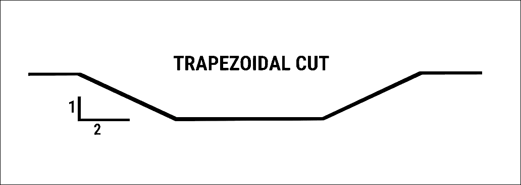
- Use trapezoid geometry: This option uses user-defined values to create a trapezoidal shape along the polygon path.
By default, the Terrain path width (flat section) is set to 50 ft (15 m). However, the user can define a new value or click the [Pick] button, and then measure a width from the Map View.

- The Side slope (V:H) ratio value is set to 1:1 by default, which corresponds to 1 ft (m) rise to a 1 ft (m) run. A ratio of 1:0 represents a vertical wall. However, many times a flatter slope is required, such as 1:2 or 1:3. The user can define the ratio to represent the slope.
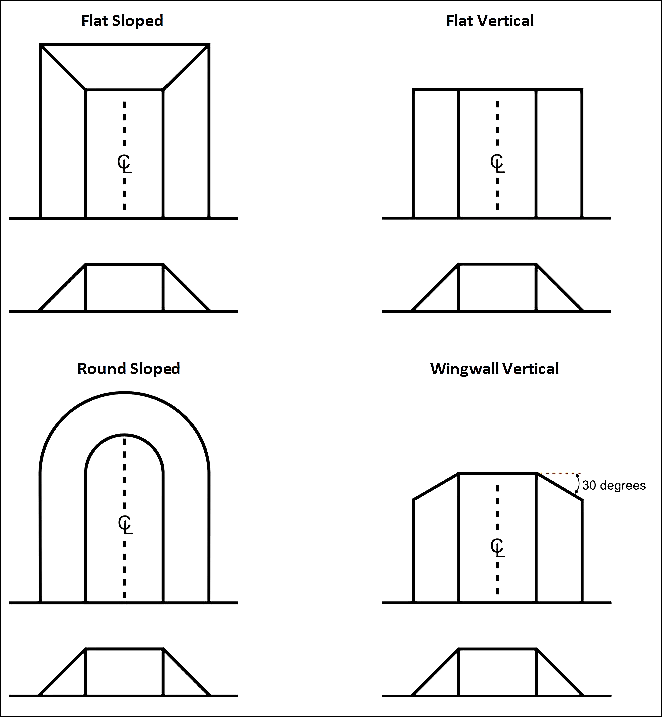
The Start path end-cap type and End path end-cap type dropdown combo boxes allow the user to choose different end cap styles from the following options:
- Flat Sloped
- Flat Vertical (default)
- Round Sloped
- Wingwall Vertical
Note that the sloped end cap option causes the defined side slope to be applied on the end cap. The vertical end cap option has no side slope and is vertical.
Modified Terrain Surface
This section is used to define the specifications of the revised terrain grid. The section contains the following options:
- Current Terrain Surface
If this radio button option is selected, then the software performs the stamping operation on the current terrain surface selected in the Terrain surface dropdown combo box. Note that selecting the Current Terrain Surface option disables the New Terrain Surface option.
- New Terrain Surface
If this radio button option is selected, then the software allows the user to create a new terrain surface to save the stamping operation into it.
Click the […] browse button for the Terrain file entry to specify the file name and directory location to which to save the revised terrain grid file.
By default, the Load terrain as map layer checkbox option is checked to load the revised terrain grid as a layer in the Map Data Layers panel. Click the pencil icon to rename the layer.
The user can select the CRS to be used for the revised terrain grid. By default, the software uses the project CRS.
The Overwrite existing terrain layer checkbox option is checked by default to automatically overwrite an existing terrain layer (if one exists) with the revised terrain layer.
After the options for stamping the terrain geometry have been defined, click the [Apply] button and the software will generate the revised terrain grid and, as an additional option, load the DEM file as a layer in the Map Data Layers panel.