
Welcome to CivilGEO Knowledge Base
Welcome to CivilGEO Knowledge Base

The culvert computational routines in HEC‑RAS require the same four cross sections as the bridge computational routines. These cross sections include:
The following figure illustrates the cross section locations at a culvert roadway crossing.

The two cross sections at the culvert ends represent the channel outside of the culvert. Separate culvert data will be used to create internal cross sections inside of the culvert. Whenever the user is computing a water surface profile through a culvert (or any other hydraulic structure); additional cross sections should always be included both upstream and downstream of the structure. This will prevent any user‑entered boundary conditions from affecting the hydraulic results through the culvert.
Cross section 1 should be located at a point where flow has fully expanded from its constricted top width caused by the culvert constriction. The cross section spacing downstream of the culvert can be based on the same criterion as used for bridge modeling. The entire cross sectional area of Cross Section 1 is typically considered to be effectively conveying flow.
Cross section 2 is located a short distance downstream from the culvert exit. This distance should represent the short distance that is required for the abrupt transition of the flow from the culvert to the channel. This cross section does not include the culvert structure or embankments, but represents the physical shape of the channel just downstream of the culvert. The roadway geometry and culvert shape and location is entered into the Bridge & Culvert Data dialog box which include this cross section as the ground geometry.
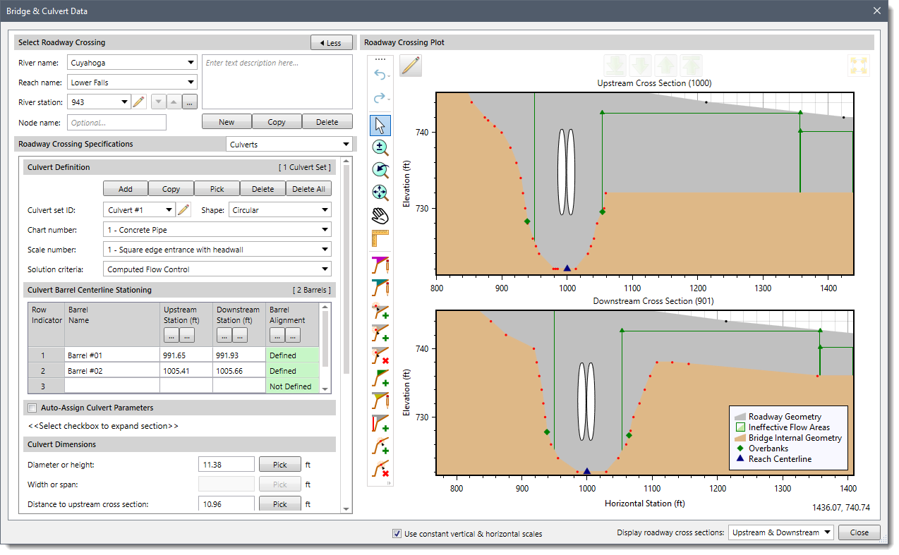
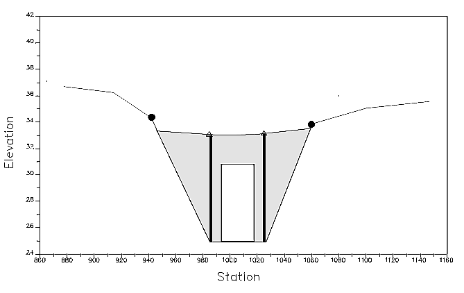
The ineffective flow area option is used to restrict the effective flow area of cross section 2 to the flow area around or near the edges of the culverts, until flow overtops the roadway. The ineffective flow areas are used to represent the correct amount of active flow area just downstream of the culvert. Because the flow will begin to expand as it exits the culvert, the active flow area at cross section 2 is generally wider than the width of the culvert opening. The width of the active flow area will depend upon how far downstream cross section 2 is from the culvert exit. In general, a reasonable assumption would be to assume a 1.5 : 1 expansion rate over this short distance. With this assumption, if cross section 2 is 6 feet from the culvert exit, then the active flow area at cross section 2 should be 8 feet wider than the culvert opening (4 feet on each side of the culvert). The figure below illustrates cross section 2 of a typical culvert model with a box culvert. As indicated, the cross section data does not define the culvert shape for the culvert model. On the below figure, the channel bank locations are indicated by small circles, and the stations and elevations of the ineffective flow areas are indicated by triangles.

Cross sections 1 and 2 are located so as to create a channel reach downstream of the culvert in which the HEC‑RAS program can accurately compute the friction losses and expansion losses downstream of the culvert.
Cross section 3 is located a short distance upstream of the culvert entrance, and represents the physical configuration of the upstream channel. This cross section should be far enough upstream from the culvert face, such that the abrupt contraction of flow has room to occur. Also, the culvert computational routines take into account the entrance loss in all of the calculations. This entrance loss requires some flow distance to occur over. The culvert computational routines use a combination of a bridge deck, cross sections 2 and 3, and culvert data, to describe the culvert(s) and the roadway embankment. The culvert data, which is used to describe the roadway embankment and culvert openings, is located at a river station between cross sections 2 and 3.
The ineffective flow area option is used to restrict the effective flow area of cross section 3 until the flow overtops the roadway. The ineffective flow area is used to represent the correct amount of active flow area just upstream of the culvert. Because the flow is contracting rapidly as it enters the culvert, the active flow area at cross section 3 is generally wider than the width of the culvert opening. The width of the active flow area will depend upon how far upstream cross section 3 is placed from the culvert entrance. In general, a reasonable assumption would be to assume a 1 : 1 contraction rate over this short distance. With this assumption, if cross section 3 is 5 feet from the culvert entrance, then the active flow area at cross section 3 should be 10 feet wider than the culvert opening (5 feet on each side of the culvert). The figure below illustrates cross section 3 of a typical culvert model for a box culvert, including the roadway profile and the culvert shape defined by the the Bridge & Culvert Data dialog box. As indicated, the ground profile does not define the culvert shape for the culvert model. On the below figure, the channel bank locations are indicated by small circles and the stations and elevations of ineffective area control are indicated by triangles.
Cross section 4 is located at a point where flow has not yet begun to contract from its unrestrained top width upstream of the culvert to its constricted top width near the culvert. This distance is normally determined assuming a 1 : 1 contraction of flow. In other words, the average rate at which flow can contract to pass through the culvert opening is assumed to be one foot laterally for every one foot traveled in the downstream direction. The entire area of Cross Section 4 is typically considered to be effective in conveying flow.


CivilGEO G2 Reviews
4.8/5.0 Rating, Over 230 Reviews

GeoHECRAS is recognized as the top Civil Engineering Design Software with an average of 4.8 out of 5.0 rating from over 230 real user reviews on G2.


We use cookies to give you the best online experience. By agreeing you accept the use of cookies in accordance with our cookie policy.
When you visit any web site, it may store or retrieve information on your browser, mostly in the form of cookies. Control your personal Cookie Services here.


