
Welcome to CivilGEO Knowledge Base
Welcome to CivilGEO Knowledge Base
This article introduces the basic concepts of culvert hydraulics, which are used in the HEC‑RAS culvert computational routines.
A culvert is a relatively short length of closed conduit, which connects two open channel segments or bodies of water. Two of the most common types of culverts are: circular pipe culverts, which are circular in cross section, and box culverts, which are rectangular in cross section. The below figure shows an illustration of circular pipe and box culverts.

Figure 1: Cross Section of a Circular Pipe and Box Culvert, Respectively
HEC‑RAS has the ability to model the following culvert shapes:
Culverts are made up of an entrance where water flows into the culvert, a barrel, which is the closed conduit portion of the culvert, and an exit, where the water flows out of the culvert, as shown in the below figure. The total flow capacity of a culvert depends upon the characteristics of the entrance as well as the culvert barrel and exit.
The tailwater at a culvert (TW in the below figure) is the depth of water at the exit or downstream side of the culvert, as measured from the downstream invert of the culvert. The invert is the lowest point on the inside of the culvert at a particular cross section. The tailwater depth depends on the flow rate and hydraulic conditions downstream of the culvert.
The headwater at a culvert (HW in the below figure) is the depth from the culvert inlet invert to the energy grade line, for the cross section just upstream of the culvert (cross section 3). The headwater represents the amount of energy head required to pass a given flow through the culvert.
The Upstream Water Surface (WSU in the below figure) is the depth of water on the entrance or upstream side of the culvert (cross section 3), as measured from the upstream invert of cross section 3.
The Total Energy at any location is equal to the elevation of the invert plus the specific energy (depth of water + velocity heady) at that location. All of the culvert computations within HEC‑RAS compute the total energy for the upstream end of the culvert. The upstream water surface (WSU) is then obtained by placing that energy into the upstream cross section and computing the water surface that corresponds to that energy for the given flow rate.
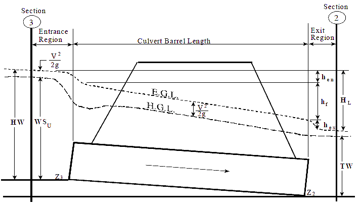
Figure 2: Full Flowing Culvert with Energy and Hydraulic Grade Lines


CivilGEO G2 Reviews
4.8/5.0 Rating, Over 230 Reviews

GeoHECRAS is recognized as the top Civil Engineering Design Software with an average of 4.8 out of 5.0 rating from over 230 real user reviews on G2.


We use cookies to give you the best online experience. By agreeing you accept the use of cookies in accordance with our cookie policy.
When you visit any web site, it may store or retrieve information on your browser, mostly in the form of cookies. Control your personal Cookie Services here.


