1. Home
  2. Knowledge Base
  3. GeoHECRAS
  4. Draw and Assign 2D Roughness Regions Command

Draw and Assign 2D Roughness Regions Command

GeoHECRAS allows the user to create their own 2D flow area roughness regions. These regions are user-defined polygons that can be used to override the base Manning’s n roughness values within that polygon. For example, the user may want to define a polygon representing the river channel so that the roughness values are more representative of the values found in the channel rather than in the overbank areas.

Creating a Roughness Region

To create a roughness region, either the Draw 2D Roughness Regions or Assign 2D Roughness Regions command can be used. Both commands work similarly.
Draw and Assign 2D Roughness Regions commands from the Manning’s Roughness dropdown menu

Draw 2D Roughness Regions Command

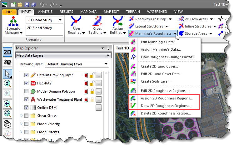
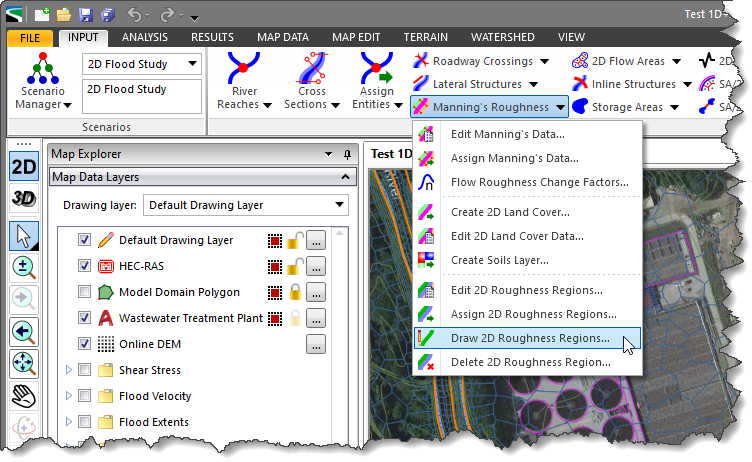
The Draw 2D Roughness Regions command allows the user to interactively draw Manning’s roughness region polygons, such as for channel areas, where the Manning’s roughness data overrides the land cover data used for 2D flow areas.

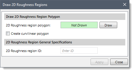
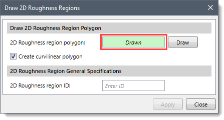
Follow the steps below to use the Draw 2D Roughness Regions command:

  1. From the Input ribbon menu, click the Manning’s Roughness dropdown menu, and then select the Draw 2D Roughness Regions command.
    Draw 2D Roughness Regions Input ribbon menu command
  2. The Draw 2D Roughness Regions dialog box will be displayed.
    Draw 2D Roughness Regions dialog box
  3. Click the [Draw] button adjacent to the 2D Roughness region polygon field. By default, the software allows the user to draw the roughness region polygon using linear segments. Use the Create curvilinear polygon checkbox to draw the polygon using curvilinear segments.
  4. The Draw 2D Roughness Regions dialog box will temporarily disappear, and a prompt will be displayed on the status bar directing the user what to do next. The user can then draw 2D roughness region polygons on the Map View. While drawing elements, the user can use the [Ctrl] key to switch between the curvilinear and the linear digitizing. Refer to this article in our knowledge base to learn more about the drawing elements on the Map View.
  5. When finished, press the [Enter] key or right-click and select Done from the displayed context menu.
  6. The software will then return the user to the Draw 2D Roughness Regions dialog box, and the status of the 2D Roughness region polygon read-only field will be changed from Not Drawn to Drawn.
    2D Roughness region polygon read-only field
  7. Provide the 2D roughness region name in the 2D Roughness region ID entry field.
  8. Click the [Apply] button, and the 2D roughness region will be created. Repeat the above steps to draw additional 2D Roughness regions.

Assign 2D Roughness Regions Command

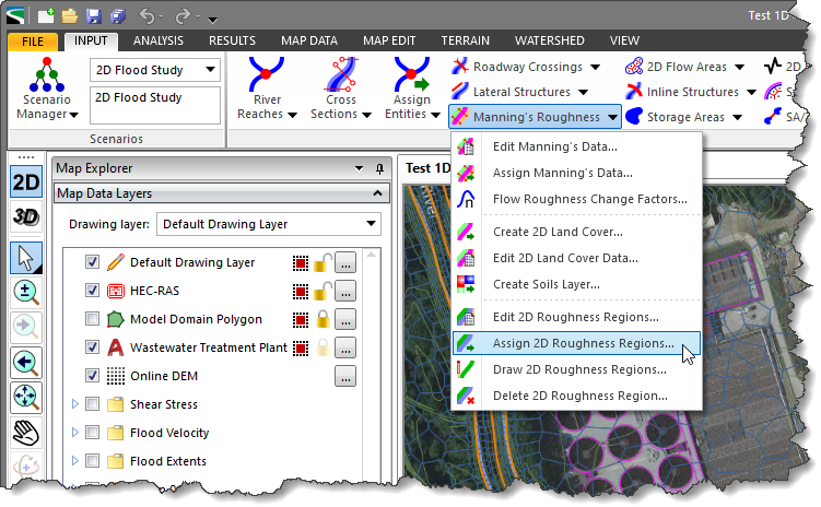
The Assign 2D Roughness Regions command allows the user to assign Manning’s roughness region from polylines and polygons, such as for channel areas, where the Manning’s roughness data overrides the land cover data used for 2D flow areas.

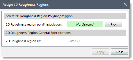
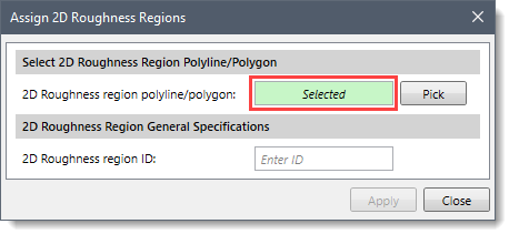
Follow the steps below to use the Assign 2D Roughness Regions command:

  1. From the Input ribbon menu, click the Manning’s Roughness dropdown menu, and then select the Assign 2D Roughness Regions command.
    Assign 2D Roughness Regions Input ribbon menu command
  2. The Assign 2D Roughness Regions dialog box will be displayed.
    Assign 2D Roughness Regions dialog box
  3. Click the [Pick] button adjacent to the 2D Roughness region polyline/polygon field.
  4. The Assign 2D Roughness Regions dialog box will temporarily disappear, and a prompt will be displayed on the status bar directing the user what to do next. The user can then select polylines or polygons from Map View.
  5. Upon selecting a polyline or polygon from the Map View, the software will then return the user to the Assign 2D Roughness Regions dialog box, and the status of the 2D Roughness region polyline/polygon read-only field will be changed from Not Selected to Selected.
    2D Roughness region polyline/polygon read-only field
  6. Provide the 2D roughness region name in the 2D Roughness region ID entry field.
  7. Click on the [Apply] button, and the software will treat the polyline or polygon as a 2D roughness region.

Assigning Manning’s Coefficient to 2D Roughness Regions

The user can utilize the Edit 2D Land Cover Data command to enter/override the Manning’s roughness coefficient for the assigned/drawn 2D roughness region(s) drawn over the existing 2D land cover layer. Refer to this article in our knowledge base for more information.

About the Author Chris Maeder

  • Was this helpful?
  • YesNo

Was this article helpful?

Related Articles