The Automated Draw Reaches command allows the user to automatically draw reaches from the user selected locations on the Map View.
Follow the steps below to use the Automated Draw Reaches command:
- From the Input ribbon menu, select the Routing Reaches dropdown menu and then choose the Automated Draw Reaches command.
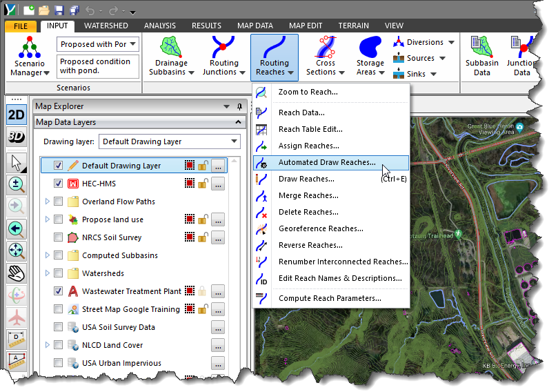
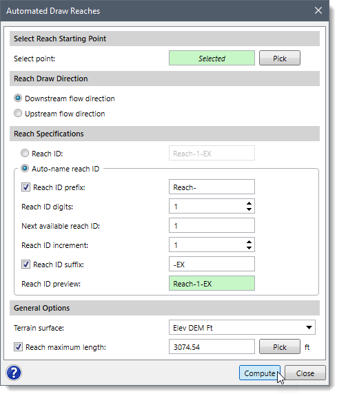
- The Automated Draw Reaches dialog box will be displayed.
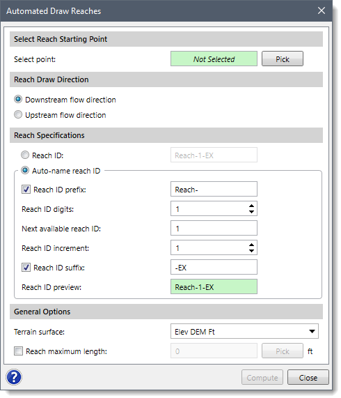
The following sections describe the Automated Draw Reaches command and how to interact with the above dialog box.
Selecting Reach Starting Point
The Select Reach Starting Point section is used to select a starting point on the Map View for drawing the reach.
To select a starting point, follow the steps below:
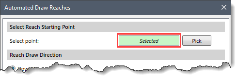
- Click on the [Pick] button, and the dialog box will temporarily disappear.
![[Pick] button](/wp-content/uploads/sites/25/2022/10/Automated-Draw-Reaches-Command-Image-3.png)
- The status bar (shown under the Map View) will prompt you to select a point on the Map View. Select the starting point on the Map View to draw the reach.
- After selecting the starting point, the user is immediately returned to the Automated Draw Reaches dialog box, and the Select point read-only field will be changed from Not Selected to Selected.
Reach Draw Direction
This section is used to define the direction of the reach polyline to be drawn based on the selected starting point.
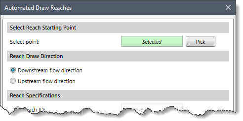
The following options are provided:
- Downstream flow direction
This radio button option is used to define the flow direction of the reach polyline downstream from the starting point. Note that this option is selected by default when the dialog box is displayed.
- Upstream flow direction
This radio button option is used to define the flow direction of the reach polyline upstream from the starting point.
Reach Specifications
This section is used to specify a reach ID for each drawn reach. The user can assign these IDs either manually or automatically using some predefined formats.
Follow the steps below to assign reach IDs to the reaches:
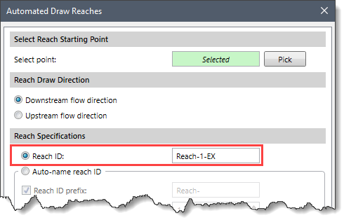
- If a reach has been drawn while the Reach ID option was enabled, the user can manually enter the reach ID in the corresponding field as shown below.
- Alternatively, the user can enable the Auto-name reach ID radio button option to automatically name newly drawn reaches as per the user’s predefined naming formats as shown below.
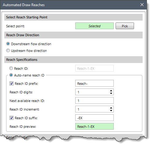
The different reach naming formats present in the Auto-name reach ID option are as follows:
- Reach ID prefix: This option allows a prefix to be added to the start of the reach ID.
- Reach ID digits: This option permits the specification of a set number of digits to use for the reach ID. For example, using 3 digits causes the reach ID to be of the format 001, 002, etc.
- Next available reach ID: This entry defines the next element ID number to be used.
- Reach ID increment: This entry defines the increment to use when numbering elements. The default value is 1.
- Reach ID suffix: This option allows a suffix to be added to the end of the reach ID.
- Reach ID preview: This entry provides a preview of the reach naming specifications defined above.
General Options
This section is used to define the general options for drawing the reach.
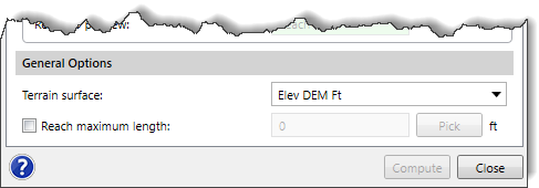
- Terrain surface
The dropdown combo box lists the terrain surfaces associated with the project which are used to define the reach polyline. By default, the current scenario’s terrain surface is selected. If there is no terrain surface defined for the selected scenario, then this entry is blank.
- Reach Maximum length
This optional checkbox option is used to define the maximum length that the reach polyline will be drawn. If left blank, the polyline will extend to the limits of the underlying flow direction grid.
Alternatively, click the
[Pick] button to draw a polyline representing the maximum reach length. On clicking the
[Pick] button, the dialog box will temporarily disappear. A prompt will be displayed on the status bar instructing the user to draw an approximate reach polyline on the Map View. When starting to draw a reach polyline by holding down the
[Shift] key, the drawing is done along an ortho line. Similarly, if the user holds down the
[Ctrl] key while drawing, the drawing is done along a curvilinear line. In addition, the status bar shows the accumulated length while drawing the reach polyline. Once finished, press the
[Enter] key or right-click and select
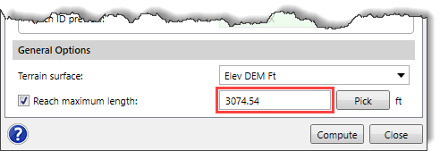
Done from the displayed context menu. The drawn polyline will be removed, and the
Automated Draw Reaches dialog box will be redisplayed with the measured distance, as shown below.
 Note
Note that the
[Pick] button will be disabled (i.e., grayed out) up until the point that the user selects a starting point.
Computing Flow Direction
When all the options have been properly defined, click the [Compute] button to compute the flow direction grid for the selected terrain surface.
While the computation is running, the [Compute] button will change to [Cancel] button, which allows the user to abort the command if needed. In addition, a progress bar at the bottom will show the progress of the computation along with status messages.
After computing the flow direction grid, the software will internally assign the created polyline as a reach on the Map View.


