Flow training structures, such as spur dikes, bendway weirs, rock vanes, bank barbs, chevrons, and revertments, can be used to maintain the channel location within a river system in order to prevent or reduce channel migration during a flood event.
These structures can also be used to provide protection to critical infrastructure, such as bridge roadway crossings, by directing river flow through the bridge opening during extreme flow events. To learn more about flow training structures, refer to this article in our knowledge base.
In GeoHECRAS, the user can define the 2D flow training structures by either drawing or assigning the polyline using the following commands:
- Draw 2D Flow Training Structures
- Assign 2D Flow Training Structures
Drawing 2D Flow Training Structures
2D flow training structures can be defined by manually drawing the polylines on the Map View using the Draw 2D Flow Training Structures command.
Follow the steps below to draw a 2D flow training structure:
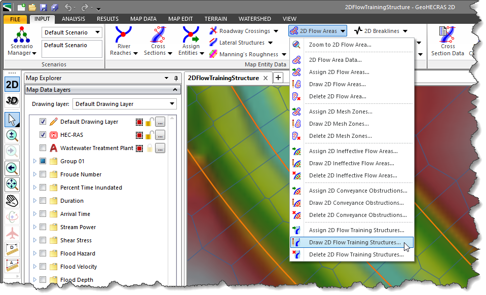
- From the Input ribbon menu, click the 2D Flow Areas dropdown menu and then select the Draw 2D Flow Training Structures command.
- The Draw 2D Flow Training Structures dialog box will be displayed.

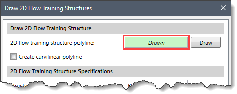
- Click the [Draw] button. Note that the user can use the Create curvilinear polyline checkbox option to draw the polyline using curvilinear segments.
![[Draw] button](/wp-content/uploads/sites/25/2022/09/2D-Flow-Training-Structures-Command-Image-3.png)
- The Draw 2D Flow Training Structures dialog box will temporarily disappear, and a prompt will be displayed on the status bar instructing the user to draw the polyline on the Map View. While drawing elements, the user can use the [Ctrl] key to switch between curvilinear and linear digitizing. Refer to this article in our knowledge base to learn more about drawing elements on the Map View.
- Draw a polyline on the Map View representing the centerline of the 2D flow training structure. You can draw the polyline either from the bank into the channel or from the channel into the bank. Make certain to extend the polyline far enough into the overbank area so that the flow structure fully intersects with the terrain surface.
- When finished, press the [Enter] key or right-click and select Done from the displayed context menu.
- The Draw 2D Flow Training Structures dialog box will be redisplayed and the status of the 2D flow training structure polyline read-only field will be changed from Not Drawn to Drawn.
- The software automatically names the drawn 2D flow training structure in the 2D Flow Training Structure Specifications section. Note that the user can also change the name to whatever is desired from the Structure name input field.
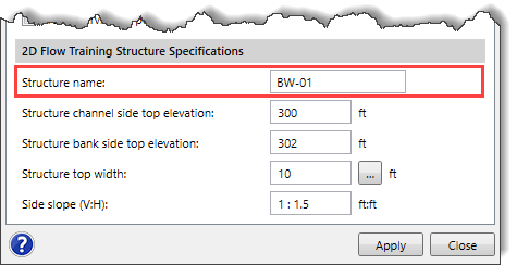
- Define the 2D flow training structure’s dimensions. 2D Flow structures can either have a weir crest that is level or sloped downward towards the channel. The software allows a sloping weir crest geometry.
- The Structure channel side top elevation entry defines the structure channel side top elevation (lower elevation near the channel).
- The Structure bank side top elevation entry defines the structure bank side top elevation (higher elevation near the bank).
- The Structure top width entry defines the structure top width (sloped top elevation). By default, the software uses a value of 10. However, the user can enter a different value or click the […] button to measure the structure top width from the Map View.
- The Side slope(V:H) entry defines the sloping angle of the structure’s sides.
- Click the [Apply] button.
- The software will then construct the 2D flow training structure.
- Repeat the above steps to draw additional flow training structures.
Assigning 2D Flow Training Structures
2D flow training structures can be defined by manually assigning the polyline(s) on the Map View using the Assign 2D Flow Training Structures command. To use this command, a polyline that can be selected for the purpose of assigning the flow training structures must already exist on the Map View.
Follow the steps below to assign the 2D flow training structures:
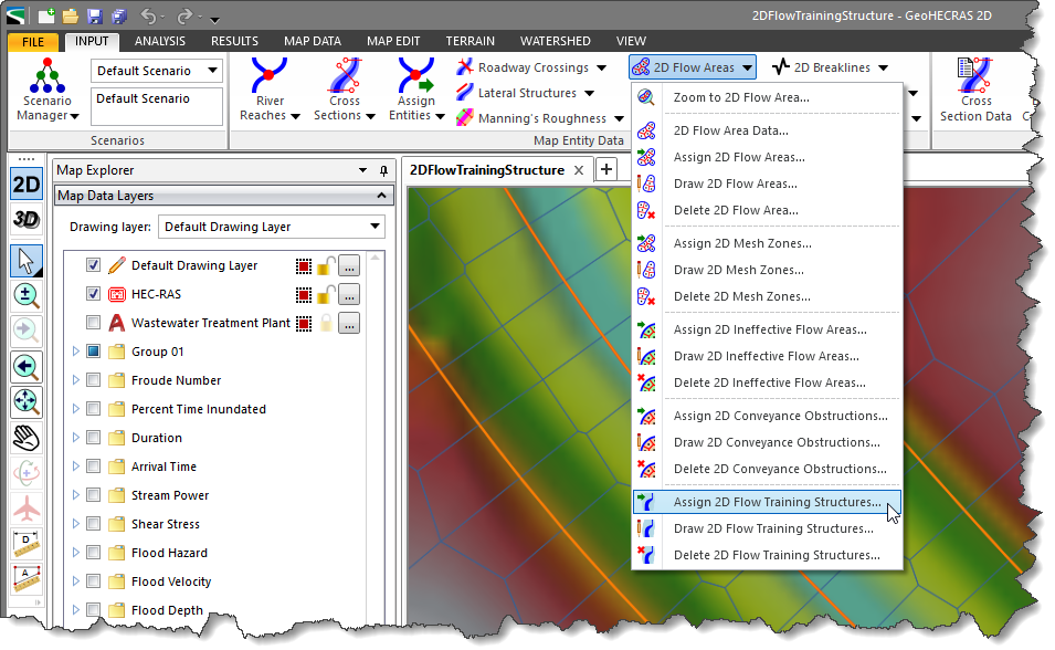
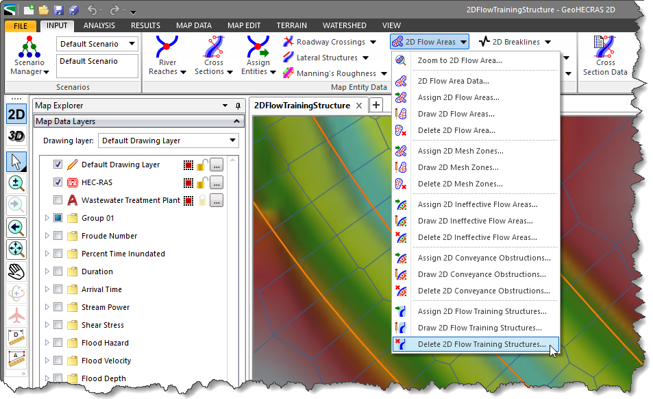
- From the Input ribbon menu, click the 2D Flow Areas dropdown menu and then select the Assign 2D Flow Training Structures command.
- The Assign 2D Flow Training Structures dialog box will be displayed.
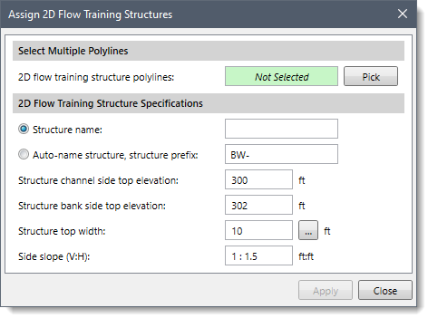
- Click the [Pick] button.
![[Pick] button](/wp-content/uploads/sites/25/2022/09/2D-Flow-Training-Structures-Command-Image-8.png)
- The Assign 2D Flow Training Structures dialog box will temporarily disappear, and a prompt will be displayed on the status bar instructing the user to select the 2d flow training structures.
- Click on the polylines in the Map View to select them. When finished, press the [Enter] key or right-click and select Done from the displayed context menu.
- The Assign 2D Flow Training Structures dialog box will be redisplayed, and the number of selected polylines will be shown in the 2D flow training structure polyline read-only field.
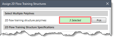 Note that if a polyline has been preselected on the Map View before running this command, the number of selected polylines will be displayed in the 2D flow training structure polylines entry.
- In the 2D Flow Training Structure Specifications section, define the prefix for the name of the 2D flow training structure in the Auto-name structure, structure prefix entry field.
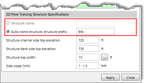 Note that the Structure name option is only available when a single polyline is selected. The user can then define the name of the 2D flow training structure in the Structure name entry field. Otherwise, the software auto-names the 2D flow training structures using the defined prefix, for example, BW-##, where ## represents the 2D flow training structures number (i.e., 01, 02, and so on) and BW represents the prefix.
- Define the 2D flow training structure’s dimensions. To learn how to define the dimensions, refer to the Drawing 2D Flow Training Structures section of this article.
- Click the [Apply] button, and the software will assign the selected polylines as 2D flow training structures.
Deleting 2D Flow Training Structures
The Delete 2D Flow Training Structures command allows the user to selectively delete the user-defined 2D flow training structures from the model.
Follow the steps below to delete the 2D flow training structures:
- From the Input ribbon menu, click the 2D Flow Areas dropdown menu and then select the Delete 2D Flow Training Structures command.
- The Delete 2D Flow Training Structures dialog box will be displayed.
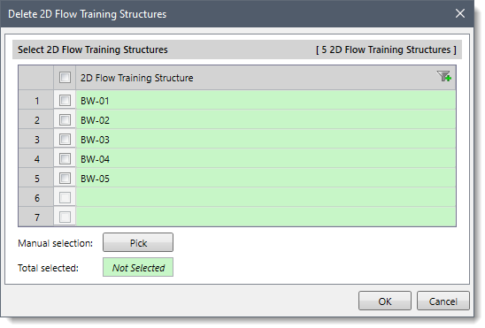
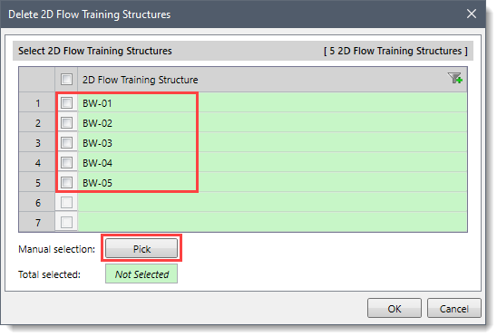
- In the 2D Flow Training Structure grid, check the checkboxes corresponding to the 2D flow training structures you want to delete. Alternatively, click the [Pick] button to select the 2D flow training structures from the Map View.
 Note that the user can click the [Select All] button to select all 2D flow training structures at once.
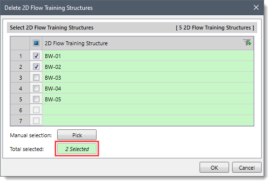
- The number of selected 2D flow training structures will be displayed in the Total selected read-only field.
 Note that the user can click the [Clear All] button to cancel the previous selection and redo the entire process.
- After selecting the 2D flow training structures, click the [OK] button, and the software will delete all the selected 2D flow training structures.


