Encroachments are activities or construction within the floodway including fill, new construction, substantial improvements, and other development. These activities are prohibited within the adopted regulatory floodway unless it has been demonstrated through hydrologic and hydraulic analyses that the proposed encroachment would not increase flood levels.
The 2D Floodplain Encroachments command automates the placement and analysis of floodplain encroachments along the river reach when performing a 2D steady or unsteady flow computation. This allows the user to have a better understanding of the true flow effects when attempting to determine the floodway in a complex flow situation. The user can also examine the DxV (Depth x Velocity) factor, as this directly indicates greater flood hazard and hydraulic importance.
Follow the steps below to use the 2D Floodplain Encroachments command:
- From the Analysis ribbon menu, select the Floodplain Encroachments dropdown menu and then choose the 2D Floodplain Encroachments command.
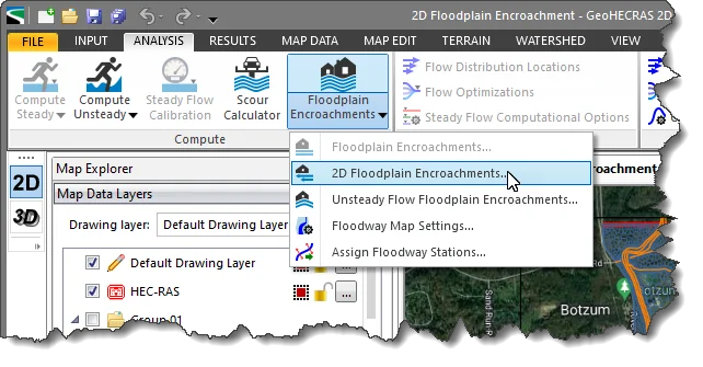
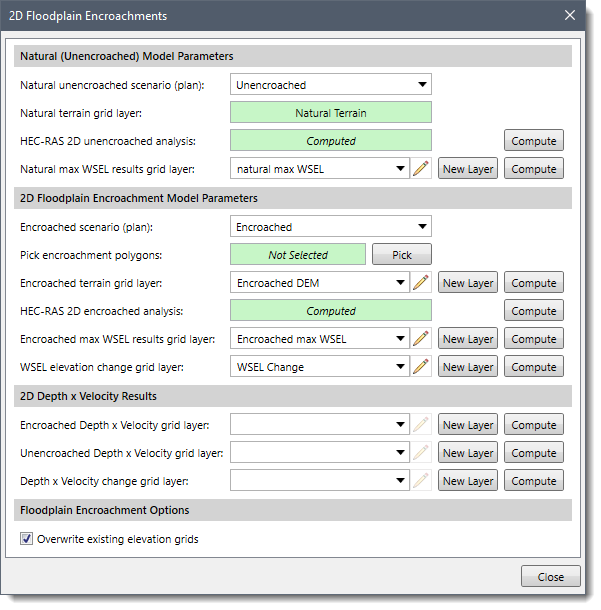
- The 2D Floodplain Encroachments dialog box will be displayed.
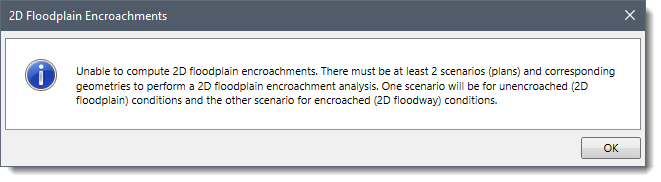
 Note that certain conditions need to be fulfilled before using the 2D Floodplain Encroachments command. If the conditions are not met, the following message will be displayed while opening the 2D Floodplain Encroachments dialog box.
The following sections describe the 2D Floodplain Encroachments command and how to interact with its dialog box.
Natural (Unencroached) Model Parameters
This section is used to define the existing flood results (water surface elevation), without any applied encroachment on the floodplain. The water surface elevation in this section is used to compute the amount of water surface rise due to floodplain encroachments.
This section contains the following entries:
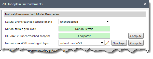
- Natural unencroached scenario (plan)
This dropdown combo box entry lists the user-defined scenarios. The user needs to select the scenario that represents the unencroached conditions. Once the unencroached scenario has been selected, the Natural terrain grid layer entry displays the 2D terrain layer associated with the scenario.
- Natural terrain grid layer
This read-only field lists the elevation grid associated with the unencroached scenario. If the unencroached model is not computed and there is no associated terrain surface for the selected scenario, the read-only field will display Undefined.
- HEC-RAS 2D unencroached analysis
This field displays the analysis status for the unencroached scenario. If the analysis of the selected scenario is already computed, the read-only field will display the status as Computed. Alternatively, the user can click the adjacent [Compute] button to compute the analysis of the scenario.
- Natural max WSEL results grid layer
This dropdown combo box entry is used to reference the natural, unencroached computed maximum water surface elevation (max WSEL) grid. If there is no existing computed water surface elevation grid layer or the existing water surface elevation grid layer data is inaccurate (e.g., out of date), the following can be performed:
- The user can click the [New Layer] button to define the name of the new grid layer to be used for storing the water surface elevation data. Alternatively, the user can select the [Add New Layer] option from the Natural max WSEL results grid layer dropdown combo box.
- The user can click the [Compute] button to compute and store the water surface elevation grid data in the newly created grid layer.
2D Floodplain Encroachments Model Parameters
This section is used to define the 2D floodplain encroachments to be applied to the model. This can be performed by selecting one or more polygons that represent the edge of the water that are desired for the encroachment. The software then uses the region outside of the polygons and raises the elevation of the terrain surface sufficiently so that the encroachments act as walls. The software then computes the analysis using this new terrain surface and computes the resultant water surface elevation grid.
The section contains the following entries:
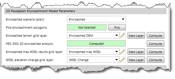
- Encroached scenario (plan)
This dropdown combo box entry lists the user-defined scenarios. The user needs to select the scenario that represents the encroached conditions. Once the encroached scenario is selected, the Encroached terrain grid layer entry displays the 2D terrain layer associated with the selected scenario.
Note that the Encroached scenario (plan) dropdown combo box does not list the scenario that is already defined in the Natural unencroached scenario (plan) dropdown combo box.
- Pick encroachment polygons
This entry is used to select the encroachment polygons from the Map View. Note that the user must select at least two polygons, one for the left overbank area and one for the right overbank area.
- Encroached terrain grid layer
This dropdown combo box lists the elevation grids associated with the selected scenario.
Note that the Encroached terrain grid layer dropdown combo box does not list the elevation grid that is already defined in the Natural terrain grid layer dropdown combo box. If there is no existing encroached terrain elevation grid assigned or if the existing encroached terrain elevation grid is inaccurate (e.g., out of date), the following can be performed.
- The user can click the [New Layer] button to define the name of the new grid layer to be used for storing the encroached terrain elevation grid. Alternatively, the user can select the [Add New Layer] option from the Encroached terrain grid layer dropdown combo box.
- The user can click the [Compute] button to compute and store the encroached terrain elevation grid data in the newly created grid layer. This computation determines the encroachment elevation to be applied to the elevation grid, which will be equal to the maximum elevation value contained within the Natural max WSEL results grid layer, plus an additional buffer of 100 feet.
- HEC RAS 2D encroached analysis
This field displays the analysis status for the encroached scenario. If the analysis of the selected scenario is already computed, the read-only field will display the status as Computed. Alternatively, the user can click the adjacent [Compute] button to compute the analysis.
- Encroached max WSEL results grid layer
The Encroached max WSEL results grid layer dropdown combo box is used to reference the encroached computed water surface elevation grid.
If there is no existing water surface elevation grid layer computed or if the existing water surface elevation grid layer data is inaccurate (e.g., out of date), the following can be performed.
- The user can click the [New Layer] button to define the name of the new grid layer to be used for storing the water surface elevation data.
- The user can click the [Compute] button to compute and store the water surface elevation grid data in the newly created grid layer.
- WSEL elevation change grid layer
The WSEL elevation change grid layer dropdown combo box lists the available elevation grid layers. However, by default, this dropdown combo box remains blank and requires the user to define a new layer to store the results. Clicking the adjacent [New Layer] button causes the software to create a placeholder layer for storing the results. Alternatively, the user can select the [Add New Layer] option from the WSEL elevation change grid layer dropdown combo box.
Clicking on the
[Compute] button causes the software to perform raster arithmetic on the below grid layers:
 Note
Note that the user can apply the coloring scheme to the contours of the resultant
WSEL elevation change grid layer to see the impact of the defined encroachment.
To learn more about HEC-RAS flood result raster grids, refer to
this article in our knowledge base.
2D Depth x Velocity Results
The Depth x Velocity (D x V) approach takes both the flood depth and velocity components to graphically show the higher conveyance areas within a calculated floodplain. This approach considers an equitable reduction in flow from either side of the flood area for a single DxV area contour.
After completing a 2D floodplain encroachment analysis, the following three resultant grid layers are obtained:
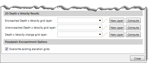
Floodplain Encroachment Options
The Overwrite existing elevation grids checkbox option is used to overwrite all the previously defined terrain grids used in this command with the newly created terrain grids.


