1. Home
  2. Knowledge Base
  3. Cross Sections
  4. Interpolate Geometry Command
  1. Home
  2. Knowledge Base
  3. GeoHECRAS
  4. Interpolate Geometry Command
  1. Home
  2. Knowledge Base
  3. HEC-RAS Data
  4. Interpolate Geometry Command
  1. Home
  2. Knowledge Base
  3. Working with a HEC-RAS Project
  4. Interpolate Geometry Command

Interpolate Geometry Command

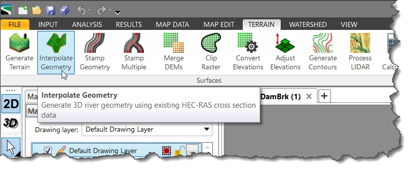
The Interpolate Geometry command allows the user to interpolate the 3D river geometry from the defined HEC-RAS cross sections and the elevation terrain DEM contained in the project. This command extends the Interpolate Cross Sections command by interpolating the 3D river geometry between defined cross sections. This functionality is quite useful when the terrain data does not contain any channel geometry. From the defined HEC-RAS cross sections, the software will interpolate the river channel geometry between the defined cross sections, burning the cross-section channel geometry into the 3D terrain data while it follows along the river reach alignment centerline.

Follow these steps to use the Interpolate Geometry command:

  1. From the Terrain ribbon menu, select the Interpolate Geometry command.
    Terrain ribbon menu - Interpolate Geometry command
  2. The Interpolate Geometry dialog box will be displayed.
    Interpolate Geometry dialog box

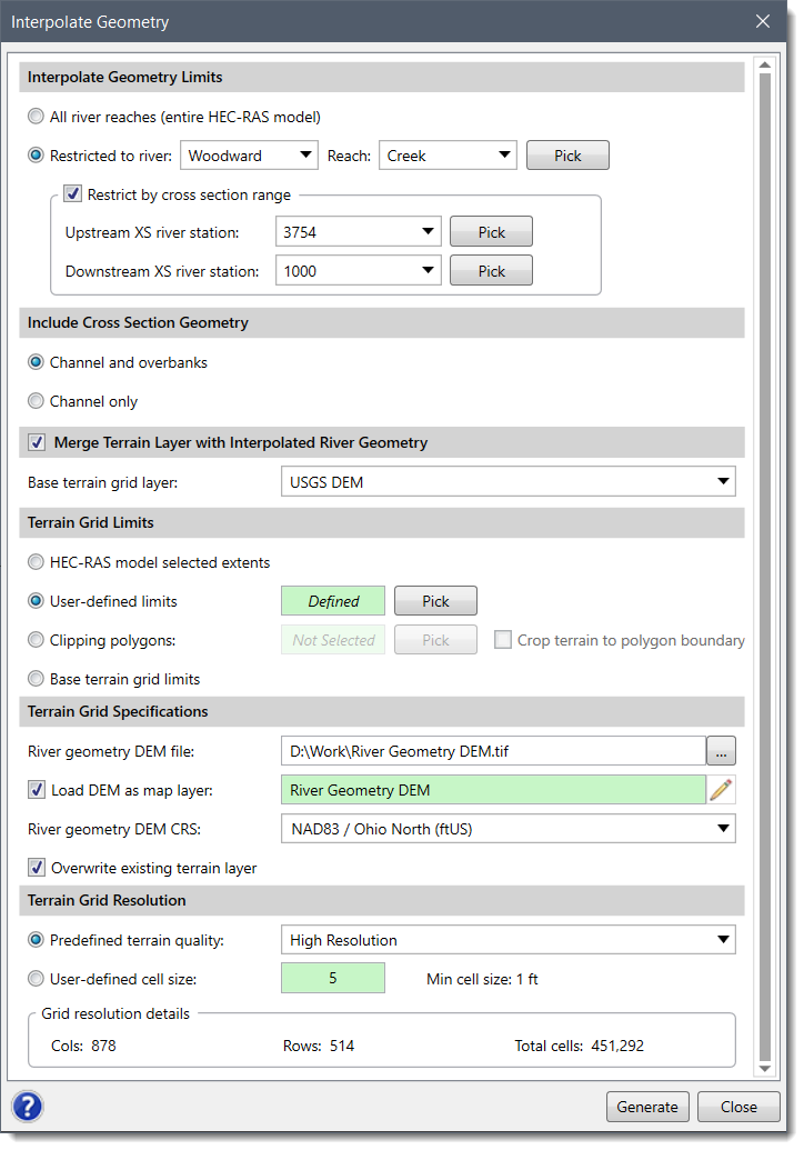
The following sections describe the Interpolate Geometry command as well as how to interact with the above dialog box.

Interpolate Geometry Limits

This section allows the user to define whether the Interpolate Geometry command should be applied to all river reaches contained within a project, or a specific river reach or portion of a river reach. For example, for a large model with numerous river reaches, this option allows the user to interpolate the river and channel geometry in a small portion of the model.

This section is used to select the river reaches and cross sections that will be used for interpolation. The following options are provided:
  • All river reaches (entire HEC-RAS model): This option causes the interpolation to be applied to river reaches within the model.
  • Restricted to river reach: The user can select a specific river reach from the dropdown entries. Alternatively, click the [Pick] button to select the river reach from the Map View.
When a single river reach has been selected, the user can choose to interpolate river geometry between selected cross sections using the Restrict by cross section range option:
  • Upstream XS river station: From the dropdown combo box, select the upstream cross section at which to end the river geometry interpolation. Alternatively, click the [Pick] button to select the cross section from the Map View.
  • Downstream XS river station: From the dropdown combo box, select the downstream cross section at which to start the river geometry interpolation. Alternatively, click the [Pick] button to select the cross section from the Map View.

Include Cross Section Geometry

This section is used to define how much of the cross section to include in the river geometry interpolation. The following options are provided:
  • Channel and overbanks: Interpolates the river geometry for the channel and overbank regions.
  • Channel only: Interpolates the river geometry from the channel only.

Merge Terrain Layer with Interpolated River Geometry

This section allows the user to merge the interpolated river geometry layer with an elevation terrain DEM. The Base terrain grid layer dropdown combo box lists all the elevation layers that are currently used in the project.

Terrain Grid Limits

This section is provided to allow the user to define the limits of the elevation terrain DEM to be computed from the river geometry interpolation. The following options are provided:
  • HEC-RAS model selected extents: This option will create a bounding rectangular region the same size as the HEC-RAS model reaches, cross sections, storage areas and 2D flow areas, plus an additional buffer boundary.
  • User-defined limits: This option allows the user to draw a rectangle on the Map View to define the limits of the river geometry interpolation. Click the [Pick] button to select the limits on the Map View. The dialog box will temporarily disappear, and an information message will be displayed on the status line. Click and drag a rectangular region on the Map View to define the elevation terrain DEM limits. After releasing the mouse button, the user will be returned to the dialog box. A layer will be created with a rectangular box drawn to represent the user-defined selected region.
  • Clipping Polygons: The user can select one or more polygons on the Map View and the software will clip the selected raster to the boundary of the polygons. The raster will set the limits of the grid to the extents of the selected polygons. For regions that are within these limits but outside the selected polygon boundary, the cells will be set to a null value.
    Click the [Pick] button to select the polygon shape region(s). The Interpolate Geometry dialog box will temporarily disappear, and a prompt will be displayed on the status bar directing the user to select the clipping polygons. Select the clipping polygons on the Map View and press the [Enter] key or right-click and select Done from the displayed context menu. The dialog box will be redisplayed. The area underneath the selected clipping polygons will be considered by the software as it processes the terrain. Additionally, the user can check the Crop terrain to polygon boundary checkbox to crop the merged terrain to the selected polygon boundary.
  • Base terrain grid limits: The interpolated river geometry elevation terrain DEM will have the same extents as the original base terrain grid. If the Merge Terrain Layer with Interpolated River Geometry section is unchecked, then this section will be unavailable (i.e., grayed out).

Terrain Grid Specifications

This section is used to specify the interpolated river geometry DEM being created.

Click the […] browse button at the River geometry DEM file entry to specify the file name and the directory location to save the interpolated river geometry DEM.

If the Load DEM as map layer checkbox option is checked then the interpolated DEM will be loaded as a layer in the Map Data Layers panel. Click the pencil icon to rename the layer. The defined layer name cannot be the same as the existing base terrain grid layer.

The River geometry DEM CRS entry is used to select the Coordinate Reference System (CRS) that the interpolated river geometry grid will be created with. This entry only lists the CRS that are used by the different layer data contained within the project and will list the project CRS as the default entry.

The Overwriting existing terrain layer checkbox option controls overwriting an existing terrain layer with the same layer name.

Terrain Grid Resolution

This section is used to define the terrain quality by specifying the grid cell size of the interpolated river geometry terrain grid being generated.

From the Predefined terrain quality entry, choose the resolution option to be used. Elevation grid resolutions range from low to ultra-high quality.

Alternatively, from the User-defined cell size entry, the user can manually define the grid cell size. The finer the grid resolution (or smaller the cell size) defined, the greater the detail that can be represented in the interpolated river geometry terrain grid.

After the river geometry options have been defined, click the [Generate] button and the software will generate the interpolated river geometry grid file and optionally load the DEM as a new layer in the Map Data Layers panel.

About the Author Chris Maeder

  • Was this helpful?
  • YesNo

Was this article helpful?

Related Articles