
Welcome to CivilGEO Knowledge Base
Welcome to CivilGEO Knowledge Base
It is quite easy to export a project to an AutoCAD or MicroStation drawing file, allowing the HEC‑RAS or HEC-HMS project data to be shared with CAD and other software.
To export a project to AutoCAD or MicroStation, select the Export HEC-RAS to CAD or Export HEC-HMS to CAD command from the Export Data dropdown menu of the Input ribbon menu. This will display the following dialog boxes:
The following sections describe how to interact with the above dialog boxes.
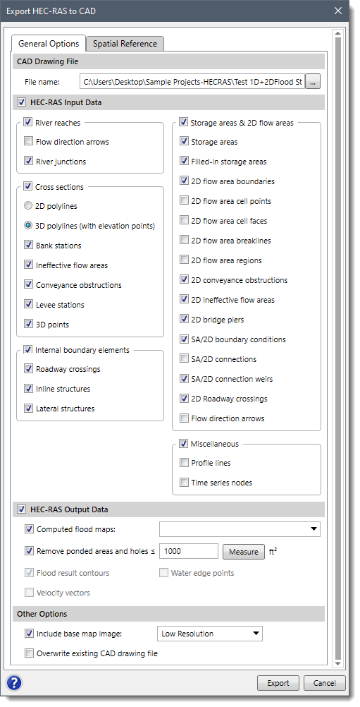
This tabbed panel is used to specify the project input and output data to be exported to CAD.
This section is used to define where the exported results are to be saved.
Click the […] button for the File name entry to specify the directory location and the drawing file name to save the exported results. Make certain to select the file type, which includes whether to save the file as an AutoCAD or MicroStation drawing file, as well as what drawing file version.
This section allows the user to select the HEC‑RAS input data to be exported. The checkbox option at the HEC-RAS Input Data section header allows the user to enable or disable the section and its underlying elements to be exported.
Each HEC‑RAS element type is placed in its own layer. For example, cross sections are placed in a cross-section layer, whereas river reaches are placed in a river reach layer. Also, 3D polyline elements, such as cross sections, are written out as 3D polylines. In addition, profile lines and time series nodes can also be exported to plot results from a 2D flow area and generate a time series plot at node, respectively.
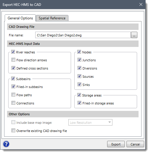
This section allows the user to select the HEC‑HMS input data to be exported. Each HEC‑HMS element type is placed in its own layer. HEC-HMS elements that can be exported to a CAD file include subbasins, river reaches, storage areas, junctions, sources, sinks, flow paths, etc.
This section allows the user to select which flood map profiles to export. The checkbox option at the HEC-RAS Output Data section header allows the user to enable or disable the section and its underlying output options to be exported. In addition, it provides the user with options to remove ponded areas and holes as well as display flood result contours, water edge points, and velocity vectors.
This section allows the user to include the base map image with a choice of imagery resolution. In addition, the Overwriting existing CAD drawing file checkbox option allows the software to overwrite an existing CAD file with the same file name.
This tabbed panel allows the user to specify the Coordinate Reference System (CRS) for the CAD drawing.
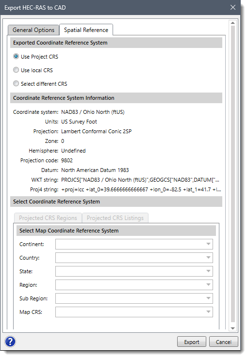
This section allows the user to select the CRS for the CAD drawing. The user can choose between the following options:
This section displays information related to the CRS of the project such as CRS units, projection and its code, CRS datum, projection file format (*.prj, *.wkt), etc.
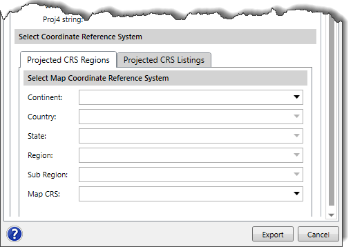
This section is used to define a custom CRS. This section gets enabled when the user has selected the Select different CRS option from the Exported Coordinate Reference System section.
To learn more about coordinate reference systems, refer to this article in our knowledge base.
After the options have been defined, click the [Export] button and the software will export the project model to CAD.
Only the current scenario (or plan) will be written out to the CAD drawing file. Separate drawing files will need to be created if multiple scenarios are to be exported to AutoCAD.


CivilGEO G2 Reviews
4.8/5.0 Rating, Over 230 Reviews

GeoHECRAS is recognized as the top Civil Engineering Design Software with an average of 4.8 out of 5.0 rating from over 230 real user reviews on G2.


We use cookies to give you the best online experience. By agreeing you accept the use of cookies in accordance with our cookie policy.
When you visit any web site, it may store or retrieve information on your browser, mostly in the form of cookies. Control your personal Cookie Services here.


