
Welcome to CivilGEO Knowledge Base
Welcome to CivilGEO Knowledge Base
In GeoHECRAS, inline structures are used to model inline dams, weirs, and gated structures with radial gates (often called tainter gates), vertical lift gates (sluice gates), overflow gates (open to the air or with a closed top), gates modeled with user-defined curves, culverts, culverts with flap gates, user-defined outlet rating curves, and user-specified outlet time series. The spillway crest of the gates can be modeled as an ogee shape or broad crested weir.
Inline structures are used to locate the centerline of hydraulic structures that span a water course (e.g., dam, weir, etc.). The inline structure should be created from left to right when looking downstream, crossing a river line exactly once.
HEC-RAS inline structures can be defined by either drawing or assigning the polyline using the following commands:
The following conditions should be met in order to draw or assign inline structure polylines:
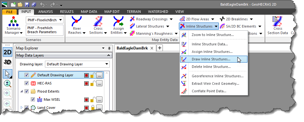
The Draw Inline Structures command is used to manually draw polylines, one-by-one, as inline structures. Generally, these polylines are drawn along the centerline of the dam structure across the river.
Follow the steps below to draw inline structures:
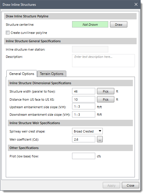
The following sections describe how to draw inline structures and interact with the above dialog box.
The Draw Inline Structure Polyline section allows the user to interactively draw individual polylines on the Map View to associate as inline structures.
The user can click the [Draw] button to interactively draw the inline structure centerline (polyline) on the Map View. Use the Create curvilinear polygon checkbox to draw the polyline using curvilinear segments.
![[Draw] button](/wp-content/uploads/sites/25/2022/03/Draw-and-Assign-Inline-Structures-Command-Image-4.png)
After clicking the [Draw] button, the Draw Inline Structures dialog box will temporarily disappear, and a prompt will be displayed on the status bar instructing the user what to do next. The user can interactively draw the inline structure polyline on the Map View. While drawing elements, the user can use the [Ctrl] key to switch between linear and curvilinear digitizing. Refer to this article in our knowledge base to learn more about drawing elements on the Map View.
When drawing the inline structure polyline, click on a starting station for the inline structure and click on station locations where the inline structure changes direction. Finally, click an ending station for the inline structure and then press the [Enter] key or right-click and select Done from the displayed context menu.
After the polyline is drawn, the dialog box will be redisplayed, and the status of the Structure centerline read-only field will change to Drawn. In addition, the drawn polyline will be highlighted on the Map View. The user can then proceed with entering the remaining data.
Note that the software is able to determine the direction of the inline structure (left to right, looking in a downstream direction) by referencing the flow direction of the underlying river reach.
This section is used to enter general specifications for the drawn inline structure.
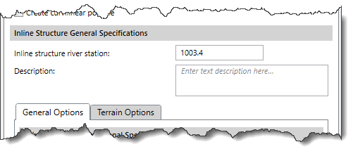
The software automatically defines the river station for the drawn inline structure polyline in the Inline structure river station numerical field. This field represents a unique value (lookup key) for the current river reach, used to identify an inline structure among other cross sections, roadway crossings, inline structures, and lateral structures.
Alternatively, the user can use the Description field to describe the current inline structure in more detail.
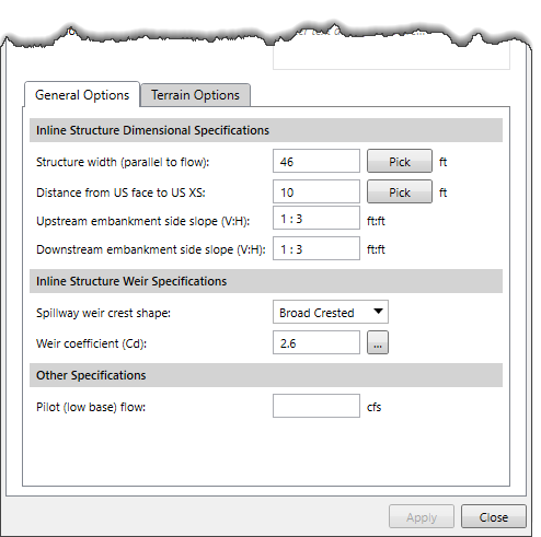
The General Options tabbed panel is used to specify the structural dimensions and weir overflow specifications of the inline structure.
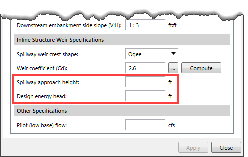
 If an ogee shaped spillway is defined, then after the Spillway Approach Height and Design Energy Head have been defined, clicking on the [Compute] button causes the software to calculate the weir coefficient at the design discharge (corresponding to the design head).
This tabbed panel is used to define the specifications for extracting the weir crest geometry of the drawn inline structure.

The user can use the Primary and Secondary Elevation Data panels to define the primary and secondary (if available in the project) elevation data sources for extracting the weir crest geometry. Depending on the selected elevation data source type, different options are provided to specify additional elevation data information.
Refer to this article in our knowledge base for information on the types of terrain elevation data that can be used.
When a secondary elevation data source is available, the software will form a concave hull around the primary elevation data source to identify its bounds. For locations where elevation data from the primary data source is unavailable, the software will use the elevation data from the secondary data source.
Note that the user cannot utilize the same data source for defining the primary and secondary elevation data.
The user can click the [Swap Sources] button to swap the selected elevation source from primary elevation data to secondary elevation data and vice versa.
If the section checkbox is unchecked, then the subsequent panels below it will be unavailable (i.e., grayed out). In addition, no geometry will be created when the inline structure is created. The inline structure will just be a flat horizontal line at elevation 0.
When the data has been defined in the Draw Inline Structure dialog box, click the [Apply] button. The software will create an inline structure where the user has drawn the centerline.
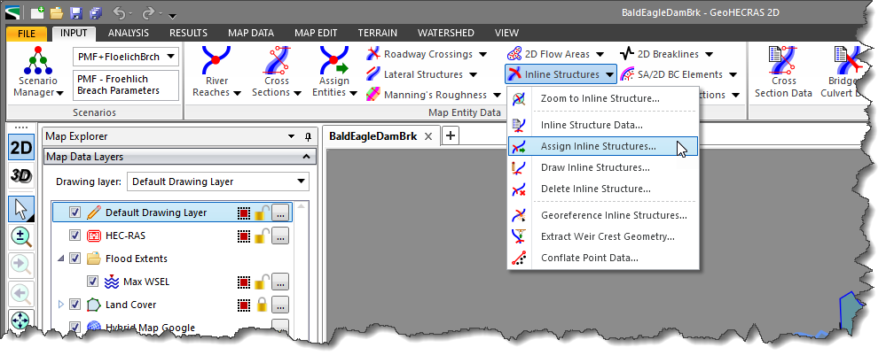
The Assign Inline Structures command is used to manually associate, one by one, previously drawn polylines as an inline flow control structure (i.e., dam). Generally, these polylines are drawn along the centerline of the structure, across the river.
Follow the steps below to assign a polyline as an inline structure centerline:
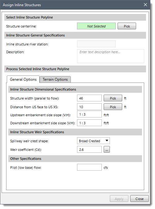
The below section describes how to associate individual polylines with specific inline structures and interact with the above dialog box.
This section allows the user to interactively select individual polylines on the Map View to be associated as inline structures.
Follow the steps below to select the inline structure polyline from the Map View:
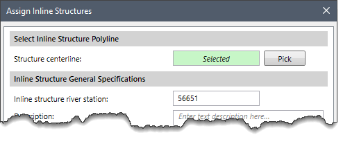
Note that if the user has first selected a polyline from the Map View before running this command, then the Structure centerline read-only field will show Selected. Otherwise, the field will show Not Selected, and the user can interactively select the inline structure polyline from the Map View.
When the data has been defined, click the [Apply] button. The software will create the inline structure and associate the selected polyline as the structure’s centerline.


CivilGEO G2 Reviews
4.8/5.0 Rating, Over 230 Reviews

GeoHECRAS is recognized as the top Civil Engineering Design Software with an average of 4.8 out of 5.0 rating from over 230 real user reviews on G2.


We use cookies to give you the best online experience. By agreeing you accept the use of cookies in accordance with our cookie policy.
When you visit any web site, it may store or retrieve information on your browser, mostly in the form of cookies. Control your personal Cookie Services here.


