A 2D flow area is a region of a model where the HEC-RAS two-dimensional flow computation algorithms will be used to calculate the flow across that region. 2D flow areas are created by constructing polygon areas representing the outer boundary of the 2D flow area and then specifying the computational mesh. Refer to this article in our knowledge base on how to draw 2D flow areas.
Once the 2D flow area is created, the user can modify the 2D flow area data. In GeoHECRAS, the 2D Flow Area Data command allows the user to view or modify the existing 2D flow area data in a project.
Follow the steps below to view or modify the 2D flow area data:
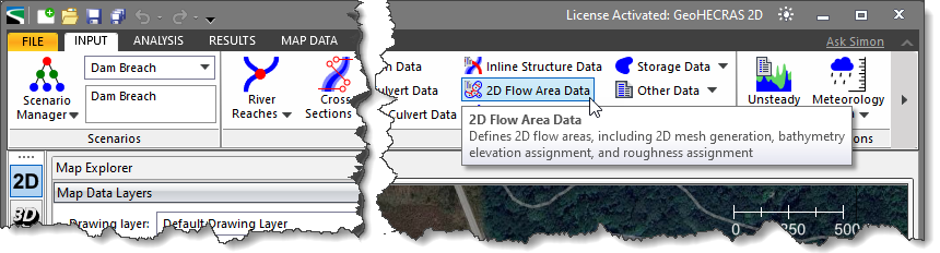
- From the Input ribbon menu, select the 2D Flow Area Data command.
 Alternatively, the user can either double-click on the 2D flow area polygon from the Map View or choose the 2D Flow Area Data command from the 2D Flow Areas dropdown menu of the Input ribbon menu.
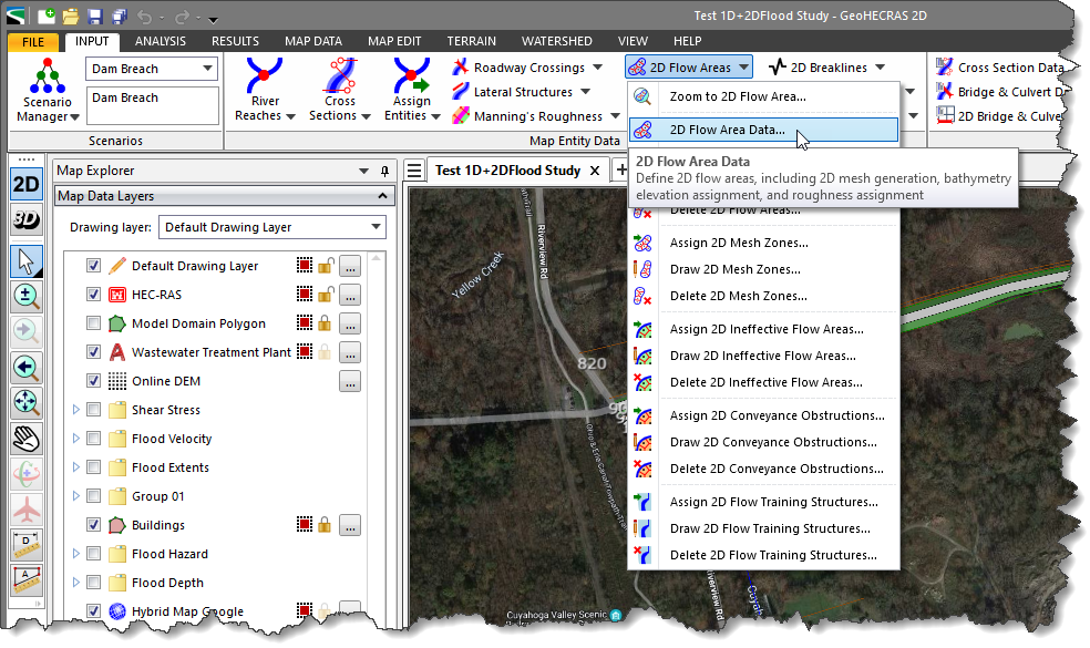
- The 2D Flow Area Data dialog box will be displayed.
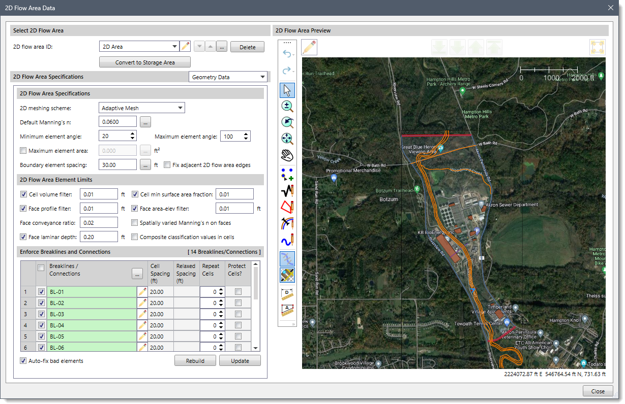
The following sections describe how to use the 2D Flow Area Data command and interact with the above dialog box.
Selecting 2D Flow Area
The Select 2D Flow Area section allows the user to select the 2D flow area name in order to define the 2D flow area data.
The following options are provided in this section:
- 2D flow area ID
This dropdown combo box lists all the 2D flow areas defined in the project. The user can select the desired 2D flow area from the dropdown combo box. Click the pencil icon to edit the 2D flow area ID. The user can navigate between the previous and next 2D flow area using the up and down arrow buttons. Alternatively, the user can click the […] button to select the 2D flow area from the Map View. Note that the up and down arrow buttons will be disabled (i.e., grayed out) when the model contains only a single 2D flow area.
- Delete
The [Delete] button is used to delete the current 2D flow area and its associated data from the project.
- Convert to Storage Area
Clicking the [Convert to Storage Area] button causes the software to convert the selected 2D flow area into a storage area.
2D Flow Area Specifications
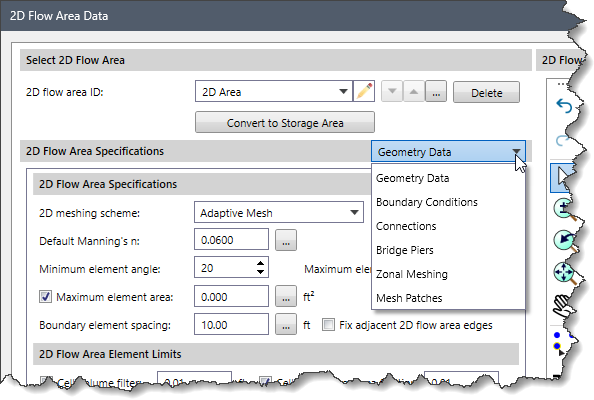
The 2D Flow Area Specifications dropdown combo box contains the following data panel entries that allow the user to define the 2D flow area data:
- Geometry Data
- Boundary Conditions
- Connections
- Bridge Piers
- Zonal Meshing
- Mesh Patches
Geometry Data Panel
This panel allows the user to define the geometry data of the current 2D flow area. By default, this data panel is shown when the 2D Flow Area Data command is selected.
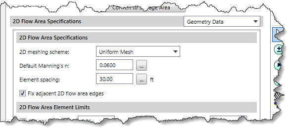
2D Flow Area Specifications
The following options are provided in this section:
- 2D meshing scheme
This dropdown combo box allows the user to select the mesh type. GeoHECRAS can create the following 2D mesh types:
- Uniform Mesh: This option divides the flow area into a grid of regular square or rectangular elements with evenly spaced nodes.
- Hexagonal Mesh: This option divides the flow area into hexagonal elements, each sharing six sides with neighboring elements and uniform size.
- Adaptive Mesh: This option adjusts the grid resolution locally based on flow characteristics.
- Default Manning’s n
This entry field is used to define a default Manning’s n value that will be used for the cell faces in the 2D flow area. By default, the software uses a value of 0.0600. However, the user can enter a different value or click the […] button to display the information table for Manning’s roughness that can be assigned.
- Minimum element angle
This spin control defines the minimum angle of the mesh element. By default, the software uses a value of 20. However, the user can enter a different value ranging from 10 to 25.
- Maximum element angle
This spin control defines the maximum angle of the mesh element. By default, the software uses a value of 100. However, the user can enter a different value ranging from 100 to 180.
- Maximum element area
This checkbox option is used to define the maximum area of the mesh element. The user can enter the area value in the entry field next to this option. Alternatively, click the […] button to measure the maximum area of the mesh element from the 2D Flow Area Preview section. By default, this checkbox option is unchecked.
- Boundary element spacing
The entry field is used to define the element spacing used in the 2D flow area generation routine. By default, the software uses a value of 30 feet. However, the user can enter a different value or click the […] button to measure the element spacing from the 2D Flow Area Preview section.
- Fix adjacent 2D flow area edges
This checkbox option is used to add internal breaklines between adjacent 2D model domains and causes adjacent 2D elements from the 2D model domains to align with each other.
Note that if the user selects a mesh type other than Uniform Mesh in the 2D meshing scheme dropdown combo box, the 2D Flow Area Specifications section will be changed as shown below.
- Element spacing
The entry field is used to define the cell spacing used in the 2D flow area generation routine. By default, the software uses a value of 100 feet. However, the user can enter a different value or click the […] button to measure the cell spacing from the 2D Flow Area Preview section.
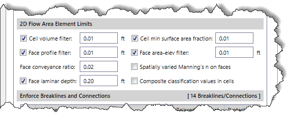
2D Flow Area Element Limits
This section is used to define the limit of the 2D flow area element.
The following options are provided in this section:
- Cell volume filter
This checkbox option is used to reduce the number of points in the 2D cell elevation volume curves that get developed in the 2D pre-processor. By default, the software uses a value of 0.01 feet. The user can also enter a different value as needed.
- Face profile filter
This checkbox option is used to reduce the number of points that get extracted from the detailed terrain for each face of a 2D cell. By default, the software uses a value of 0.01 feet. The user can also enter a different value as needed.
- Face conveyance ratio
This entry field is used to figure out if more or less points are required at the lower end of the face property tables. The software first computes conveyance at all of the elevations in the face property tables. Then it computes the conveyance at an elevation halfway between the points and compares this value to that obtained by using linear interpolation. If the computed value produces a conveyance within 2% (0.02) of the linear interpolation value, then no further points are needed between those two values. If it is more than 2%, then a new point is added to that table. This reduces the error in computing hydraulic properties, and therefore conveyance due to linear interpolation of the curves. By default, the software uses a value of 0.02.
- Face laminar depth
This checkbox option is used to define the depth of water at which turbulent flow would transition to laminar flow for sheet flow flowing over a plane. By default, the software uses a value of 0.20 feet. The user can also enter a different value as needed.
- Cell min surface area fraction
This checkbox option is used to define the fraction that is multiplied by the cell area to establish a minimum area at the lowest elevation of the cell. It prevents the cell elevation volume curves from going down to an extremely small area at the bottom of the cell, at which point it creates a curve that is very abrupt at the lowest end. Establishing a reasonable minimum area for the cell helps to ensure the stability of solving that cell when it first starts to get water. By default, the software uses a value of 0.01 percent. The user can also enter a different value as needed.
- Face area-elev filter
This checkbox option is used to reduce the number of points in the cell face hydraulic property tables. By default, the software uses a value of 0.01 feet. The user can also enter a different value as needed.
- Spatially varied Manning’s n on faces
This checkbox option allows the spatial variation in Manning’s n values to be extracted horizontally along the face of 2D cells.
- Composite classification values in cells
This checkbox option allows the land classification values to be spatially composited over each cell rather than a single point value at the center.
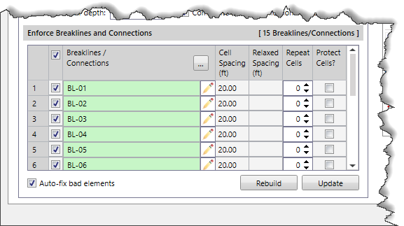
Enforce Breaklines and Connections
This section is used to create cells that are aligned with the breaklines, which ensures that flow cannot move across that cell’s face until the water surface is higher than the terrain along that breakline. The software will create cells spaced along the breakline at the nominal cell size entered by the user.
The following options are provided in this section:
- Breaklines/Connections
This entry allows the user to add additional breaklines/connections to align 2D mesh cell faces with the breaklines and prevent cells from crossing the breakline. The user can either check the Breaklines/Connections checkbox to select all breaklines/connections or manually check corresponding checkbox entries that are to be added. Alternatively, click the […] button to select breaklines/connections from the 2D Flow Area Preview section. Click the pencil icon to edit the breaklines/connections ID.
- Cell Spacing (ft)
This entry represents cell spacing along the breakline. If this entry is left blank, then the cell spacing used in the vicinity of the breakline will be used. By default, the software uses a value of 20. However, the user can enter a different value as needed.
- Relaxed Cell Spacing (ft)
This entry represents the cell spacing further away from the breakline. If this entry is left blank, then the cell spacing used in the vicinity of the breakline will be used. This value should not be the same as the Cell Spacing value or cell errors may be introduced along the breakline.
- Repeat Cells
This spin control causes additional layers of identically sized cells to be created adjacent to the breakline cells. For example, if the user entered a cell spacing of 50 feet, then the cells on both sides of the breakline would be 50 feet cells.
- Protect Cells?
This entry causes the software to leave any manual edits of the cells that align with the breakline as they are.
- Rebuild
The [Rebuild] button causes the software to recreate the entire 2D mesh using all the defined features. Any user edits to the 2D mesh elements are discarded.
- Update
The [Update] button causes the software to update the 2D flow area including all user-defined edits to the 2D mesh elements.
- Auto-fix bad elements
This checkbox option will cause the software to correct any malformed 2D elements.
Boundary Conditions Panel
This panel provides a table listing all of the boundary condition lines linked to the current 2D flow area, allowing editing and defining of the boundary conditions.
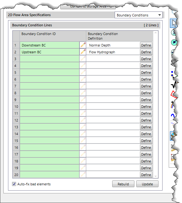
Boundary Condition Lines
The following data columns are provided:
- Boundary Condition ID
This read-only column lists the ID of the connected boundary condition lines. Click the pencil icon to edit the ID of boundary condition lines.
- Boundary Connection Definition
This column details the boundary condition lines. The following details are provided in this entry based upon the selected boundary condition types:
- Normal Depth
- Rating Curve
- Flow Hydrograph
- Stage Hydrograph
In addition, a
[Define] button is provided. Clicking this button closes the
2D Flow Area Data dialog box and then displays the
Unsteady Flow Data dialog box detailing the selected boundary conditions. Refer to
this article in our knowledge base to learn more about defining the boundary condition lines.
Note that the Rebuild button, Update button, and Auto-fix bad elements checkbox functionalities are similar to that of the Enforce Breaklines and Connections section of the Geometry Data panel.
Connections Panel
This panel defines connections and references to the currently selected 2D flow area.
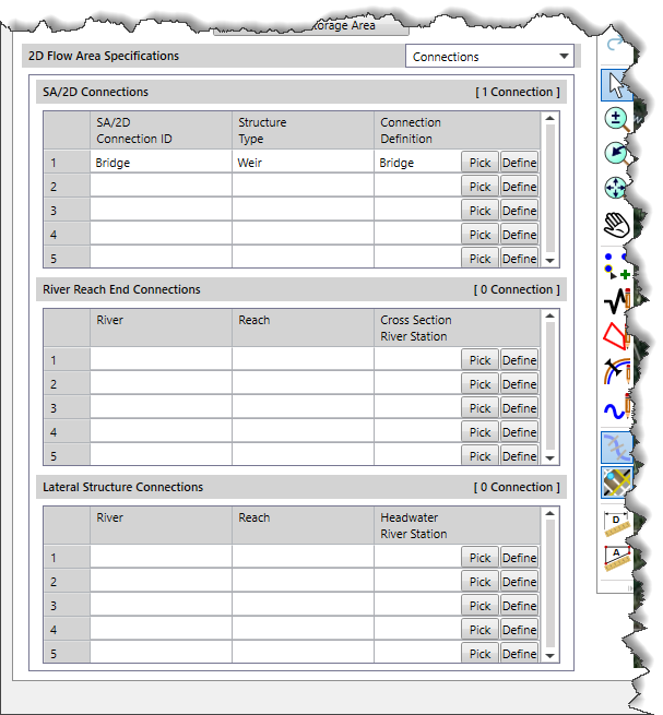
SA/2D Connections
This section provides a table listing all of the SA/2D connections linked to the current 2D flow area. This allows the 2D flow area to daisy chain to other 2D flow areas.
The following data columns are provided:
- Storage Area Connection ID
This read-only column lists the ID of the connected SA/2D connection.
- Structure Type
This read-only column lists the type of SA/2D connection that is being used. The following SA/2D connection types are available:
- Weir
- Weir and Culverts
- Weir and Gates
- Linear Routing
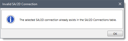
- Connection Definition
This column details the SA/2D connection. Click the [Pick] button to select the SA/2D connection from the Map View. Note that if the selected SA/2D connection already exists in a different row within the table, the following informational dialog box will be displayed.
 In addition, a [Define] button is provided. Clicking this button closes the 2D Flow Area Data dialog box and then displays the SA/2D Connections Data dialog box detailing the selected SA/2D connection. Refer to this article in our knowledge base to learn more about the SA/2D Connections Data dialog box.
River Reach End Connections
This section provides a table listing river reaches connected to the current 2D flow area.
The following data columns are provided:
- River & Reach
These two read-only columns list the river and corresponding reach that is connected to the selected 2D flow area.
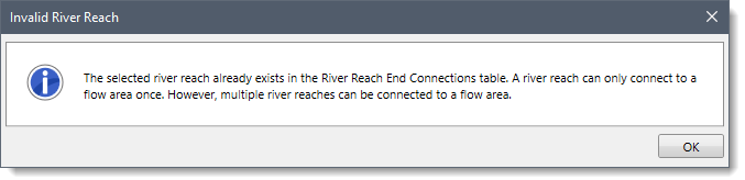
- Cross Section River Station
This read-only column details the cross section river station that is connected to the 2D flow area. Click the [Pick] button to select the river reach connecting to the 2D flow area from the Map View. Note that if the selected river reach already exists in a different row within the table, the following informational dialog box will be displayed.
 In addition, a [Define] button is provided. Clicking this button closes the 2D Flow Area Data dialog box and then displays the Cross Section Data dialog box detailing the selected cross section. Refer to this article in our knowledge base to learn more about the Cross Section Data dialog box.
Lateral Structure Connections
This section provides a table listing lateral structures connected to the current 2D flow area.
The following data columns are provided:
- River & Reach
These two read-only columns list the river and corresponding reach that are connected to the 2D flow area.
- Headwater River Station
This read-only column details the lateral structure headwater river station that is connected to the 2D flow area. Click the [Pick] button to select the lateral structure connecting to the 2D flow area from the Map View. Note that if the selected lateral structure already exists in a different row within the table, the following informational dialog box will be displayed.
In addition, a
[Define] button is provided. Clicking this button closes the
2D Flow Area Data dialog box and then displays the
Lateral Structure Data dialog box detailing the selected lateral structure. Refer to
this article in our knowledge base to learn more about the
Lateral Structure Data dialog box.
Bridge Piers Panel
This panel allows the user to model bridges (without pressure or roadway overflow) by allowing the user to “stamp” in pier structures into the 2D flow area mesh.
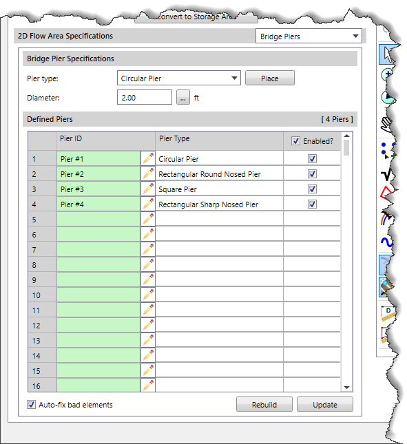
Bridge Pier Specifications
The following options are provided in this section:
- Pier type
This dropdown combo box is used to select the type of bridge pier. The following options are available in the dropdown combo box:
- Circular Pier
- Rectangular Round Nosed Pier
- Rectangular Sharp Nosed Pier
- Rectangular Square Nosed Pier
- Square Pier
The user can click the [Place] button to place the defined pier on Map View available under the 2D Flow Area Preview section. After clicking the [Place] button, the user can select the desired pier location on the Map View. The software immediately places the pier within the 2D flow area and lists it in the table available in the Defined Piers section. The software automatically assigns a default name to each new pier added to the table and incremented sequentially for each additional pier.
The software also allows the user to relocate the selected pier within the Map View. In addition, the user can rotate and resize the pier shape by pressing the [F2] function key.
- Diameter
This entry field is used to define the diameter of the bridge pier. By default, the software uses a value of 2 feet. However, the user can enter a different value or click the […] button to measure the pier diameter from the 2D Flow Area Preview section.
Note that if the user selects the Square Pier type in the Pier type dropdown combo box, the Bridge Pier Specifications sections will be modified as shown below:
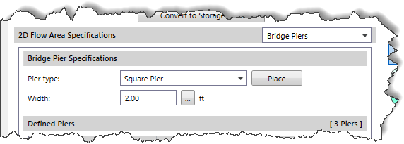
- Width
This entry field is used to define the width of the bridge pier. By default, the software uses a value of 2 feet. However, the user can enter a different value or click the […] button to measure the pier width from the 2D Flow Area Preview section.
Note that if the user selects the Rectangular Pier type in the Pier type dropdown combo box, the Bridge Pier Specifications sections will be modified as shown below:
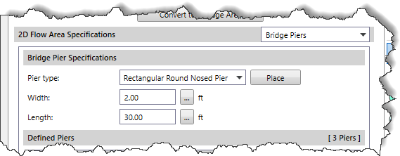
- Length
This entry field is used to define the length of the bridge pier. By default, the software uses a value of 30 feet. However, the user can enter a different value or click the […] button to measure the pier length from the 2D Flow Area Preview section.
Defined Piers
The following data columns are provided:
- Pier ID
This column displays the pier name. The user can click the pencil icon to edit the pier name.
- Pier Type
This column displays the shape of the pier.
- Enabled
This checkbox column allows the user to position pier structures into the 2D flow area mesh. The user can either check the column header checkbox to select all piers or manually check corresponding checkbox entries that are to be positioned into the 2D flow area mesh.
Note that the Rebuild button, Update button, and Auto-fix bad elements checkbox functionalities are similar to that of the Enforce Breaklines and Connections section of the Geometry Data panel.
Zonal Meshing Panel
This panel is used to define mesh zones within a 2D flow area, where each zone can have its own mesh type and corresponding parameters (e.g., element size, etc.). This allows the user to define refinement regions for specific areas of interest. For example, in a critical infrastructure area, a mesh zone could be defined, and a much smaller element size used to capture the flow direction and velocities that occur during a flood event.
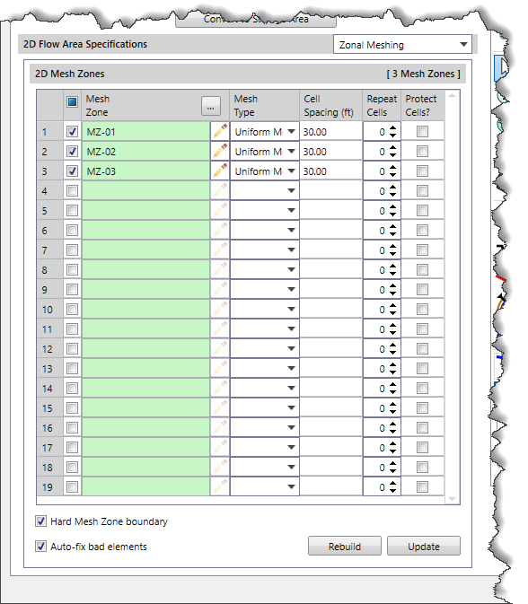
2D Mesh Zones
The following data columns are provided:
- Mesh Zone
This column displays the mesh zone name. Alternatively, click the […] button to select the mesh zone from the 2D Flow Area Preview section. The user can click the pencil icon to edit the mesh zone name.
- Mesh Type
This column displays the mesh type. The following options are available in the dropdown combo box:
- Uniform Mesh
- Hexagonal Mesh
- Adaptive Mesh
The Hard Mesh Zone boundary checkbox option enforces the boundary of mesh zones to be treated much like a breakline.
Note that the Cell Spacing column, Repeat Cells column, Protect Cells column, Rebuild button, Update button, and Auto-fix bad elements checkbox functionalities are similar to that of the Enforce Breaklines and Connections section of the Geometry Data panel.
Mesh Patches Panel
This panel allows the user to refine or coarsen an area of the mesh to model the flow more accurately. A polygon is created to define the boundaries of the mesh patches. Mesh patches can be used to densify an area where more detailed results are required, such as rapid changes in terrain or water surface elevation, or to simplify an area where the water surface elevation will not vary much, and users want to reduce the number of computation points in the 2D flow area.
In addition, mesh patches can also be used to create a functional mesh in the main channel regions of the model.
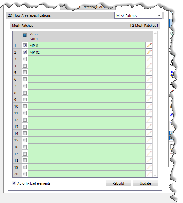
Mesh Patches
The Mesh Patch column displays the mesh patch name. The user can click the pencil icon to edit the mesh patch name.
Note that the Rebuild button, Update button, and Auto-fix bad elements checkbox functionalities are similar to that of the Enforce Breaklines and Connections section of the Geometry Data panel.
To learn how to add mesh patches in a 2D flow area, refer to this video in our knowledge base.


