
Welcome to CivilGEO Knowledge Base
Welcome to CivilGEO Knowledge Base
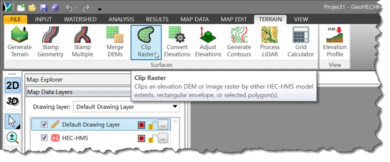
The Clip Raster command allows the user to clip an elevation DEM or image to any shape. All areas of the raster outside of the clipped region are set to a NODATA transparent value. This functionality helps by being able to trim an elevation DEM to the limits of a LIDAR field survey, allowing the user to merge in additional elevation data for the areas outside of the survey limits.
Follow the steps below to use the Clip Raster command:
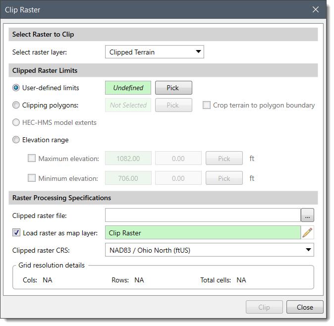
The following sections describe the Clip Raster command and how to interact with the above dialog box.
This section controls the selection of a raster layer such as a DEM or image raster for clipping based on either the model extents, rectangular envelope, or the polygons.
From the Select raster layer dropdown combo box, select the elevation DEM, or image raster that needs to be trimmed into a smaller elevation grid.
This section allows the user to define the extents of the clipped raster.
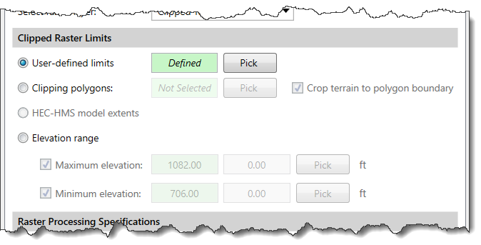
The following options are available to define the grid limits on the selected elevation grid:
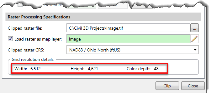
This section is used to define the specifications for the clipped raster.
Click the […] button beside the Clipped raster file entry to specify the file name and directory location to which to save the clipped raster file.
Different file formats are available to save the clipped raster file based on the type of raster layer selected. For example, if the selected raster layer is an elevation DEM, then only elevation grid file types are provided for saving the clipped raster. Similarly, if the selected raster layer is an image, then only image raster file types are provided for saving the clipped raster.
By default, the Load raster as map layer checkbox option is checked to load the clipped raster as a layer in the Map Data Layers panel. Click the pencil icon to rename the layer.
The user can select the CRS to be used for the clipped raster file. If there is only one CRS in the project, the software automatically selects it.
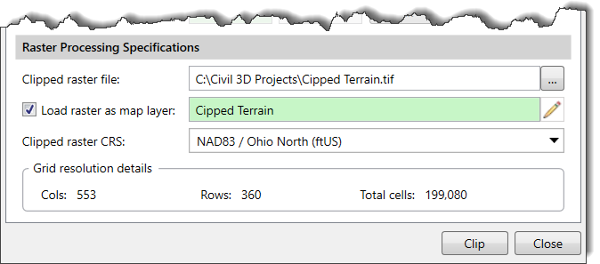
Note that if the clipped raster is an elevation DEM, then grid resolution details will show columns, rows and total cells. If the clipped raster is an image raster, however, then grid resolution details will display width, height, and color depth as shown below.
After the options have been defined, click the [Clip] button. The software will clip the raster file and create a new raster layer at the specified location. If the Load raster as Map layer checkbox was checked, the newly created raster layer will be loaded in the Map Data Layers panel.


CivilGEO G2 Reviews
4.8/5.0 Rating, Over 230 Reviews

GeoHECRAS is recognized as the top Civil Engineering Design Software with an average of 4.8 out of 5.0 rating from over 230 real user reviews on G2.


We use cookies to give you the best online experience. By agreeing you accept the use of cookies in accordance with our cookie policy.
When you visit any web site, it may store or retrieve information on your browser, mostly in the form of cookies. Control your personal Cookie Services here.


