For stormwater projects, GeoSTORM software allows the user to create, edit, analyze, and review an unlimited number of variations to the project’s scenarios (or plans). Each project scenario associates a specific geometry model, storm data, and a set of analysis specifications with a specific condition or circumstance, such as pre-developed and post-developed phases of a project. This allows the user to work with multiple scenarios in a single project and analyze computational results as different parameters are applied to the project.
Elements of a Project
The following data are used to construct a complete stormwater project within a scenario:
- Geometry data – Defines the geometric representation of a model.
- Storm data – Defines precipitation data.
- Analysis specifications – Defines the configuration for start time, end time, and time interval.
- Model calibration data – References the above files when performing an analysis.
Selecting Active (Current) Scenarios
In GeoSTORM software, the Input ribbon menu displays the Scenario ID of the currently selected scenario. The read-only field below the Scenario ID dropdown combo box displays the description of the current scenario.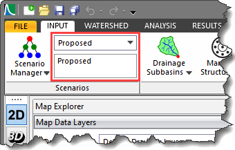
The Scenario ID dropdown combo box allows the user to quickly switch between scenarios. Moving from one scenario to another will cause the contents of the Map View to change to represent the geometry of the selected scenario.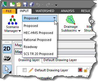
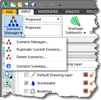
From the Input ribbon menu, expand the Scenario Manager dropdown combo box and the following commands will be displayed:
- Scenario Manager
- Duplicate Current Scenario
- Delete Scenarios
- Scenario Summary
Scenario Manager
Selecting the Scenario Manager command will display the below dialog box. The Scenario Manager dialog box displays the details of the currently selected scenario in the project.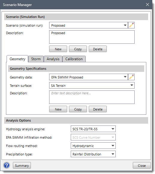
This dialog box is used to manage geometry data, storm data, analysis specifications and model calibration data associated with the current scenario. In addition, a new scenario, geometry model, storm model, and analysis specifications can be created, as well as copied from an existing scenario.
The following sections describe how to use the Scenario Manager command and interact with the above dialog box.
Scenario (Simulation Run)
This section allows the user to create new scenarios as well as manage existing scenarios. The Scenario (simulation run) dropdown combo box lists all the scenarios in the project. The user can select the preferred scenario to view or modify its corresponding data. The other sections of the dialog box will be updated based on the user’s selection.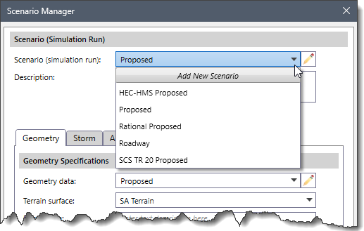
To create a new scenario, the user can select the Add New Scenario option from the Scenario (simulation run) dropdown combo box or alternatively, click the [New] button in the section. This will apply the default settings to the other sections of the Scenario Manager dialog box. The user can then specify the details for geometry, storm, analysis, and calibration in their respective sections.
To copy the current scenario for use in another scenario, the user can click the [Copy] button. To delete the currently selected scenario, the user can click the [Delete] button.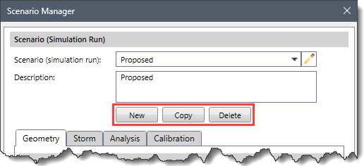
Geometry
The Geometry panel outlines the geometry data (i.e., subbasins, pipes, routing reaches, manholes, junctions, 2D mesh, etc.) that defines a model.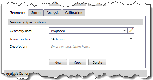
The Geometry data dropdown combo box lists all existing geometry models in the current project. In addition, the adjacent Edit icon allows the user to edit the selected geometry model ID.
The Terrain surface dropdown combo box lists the existing terrain surfaces in the project. Note that the user can select the blank option from the Terrain surface dropdown combo box to disassociate a terrain surface from the selected geometry model.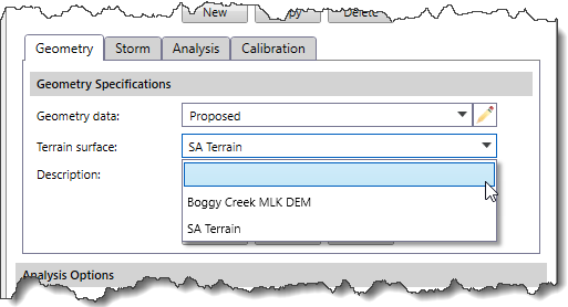
The user can define a new geometry model, copy the details of an existing geometry model to use in another geometry model, and delete the selected geometry model using the [New], [Copy], and [Delete] buttons, respectively.
Storm
The Storm panel outlines the storm specifications (i.e., rainfall, distribution, etc.) that define the boundary conditions applied to the model.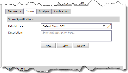
The Rainfall data dropdown combo box lists all the existing storm models in the current project. Any descriptive information about the storm model can be included in the Description text box.
The user can define a new storm model, copy the details of an existing storm model to use in another storm model, and delete the selected storm model using the [New], [Copy], and [Delete] buttons, respectively.
Analysis
The Analysis panel defines the analysis specifications that are used in running the stormwater analysis for the defined model.
The Analysis data dropdown combo box lists all the existing analysis specifications in the current project. Any descriptive information about the analysis specification can be included in the Description text box.
The user can define a new analysis specification, copy the details of an existing analysis specification to use in another analysis specification, and delete the selected analysis specification using the [New], [Copy], and [Delete] buttons, respectively.
Note that the Analysis panel is disabled (i.e., grayed out) when the Rational Method option is selected in the Hydrology analysis engine dropdown combo box of the Analysis Options section.
Calibration
The Calibration panel is used to define the model calibration data.
The following entries are available in this panel:
- Calibration type
- Calibration multiplier (ratio)
Calibration type
The Calibration type dropdown combo box allows the user to select the type of calibration to aid the simulation run.
Note that the Calibration panel is enabled only when the SCS TR-20/TR-55 option is selected from the Hydrology analysis engine dropdown combo box of the Analysis Options section.
The following options are available in this dropdown combo box:
- None (default)
- Flow
- Precipitation

Calibration multiplier (ratio)
The Calibration multiplier (ratio) spin control defines the multiplication ratio to be applied to the data. By default, this entry is listed as 1.000. The spin control will go up and down in increments of 0.010.
Analysis Options
The Analysis Options section is used to define analysis options within a project.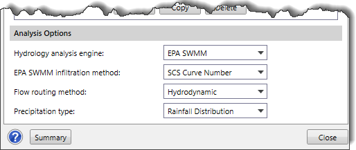
The following entries are used to define the analysis options:
- Hydrology analysis engine
- EPA SWMM infiltration method
- Flow routing method
- Precipitation type
Hydrology analysis engine
This dropdown combo box defines the hydrology method to be used in the project. Note that the default selection is determined by the option defined in the Analysis Options section of the Options backstage page.
The following options are available:
- EPA SWMM
- Modified Rational
- Rational Method
- SCS TR-20/TR-55

EPA SWMM infiltration method
This dropdown combo box defines the EPA SWMM infiltration method to be used in the project. Note that the default selection is determined by the option defined in the Analysis Options section of the Options backstage page.
The following options are available:
- Green Ampt
- Horton
- Modified Green Ampt
- Modified Horton
- SCS Curve Number

Note that the EPA SWMM infiltration method dropdown combo box is enabled only when the EPA SWMM option is selected from the Hydrology analysis engine dropdown combo box.
Flow routing method
This dropdown combo box entry defines the routing method to be used in the project. The following options are available in this dropdown combo box:
- Hydrodynamic
- Kinematic Wave
- Steady State Peak Flow

Note that the default selection is determined by the option defined in the Analysis Options section of the Options backstage page.
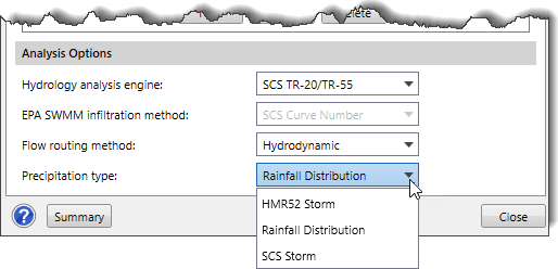
Precipitation type
This dropdown combo box entry defines the precipitation type to be used in the project. Note that the default selection is determined by the option defined in the Analysis Options section in the Options backstage page.
Note that the options displayed in the Precipitation type dropdown combo box will change based on the option selected in the Hydrology analysis engine dropdown combo box.
If the user selects the EPA SWMM option in the Hydrology analysis engine dropdown combo box, the following options will be displayed in the Precipitation type dropdown combo box.
- Rain Gage
- Rainfall Distribution

If the user selects the SCS TR-20/TR-55 option in the Hydrology analysis engine dropdown combo box, the following options will be displayed in the Precipitation type dropdown combo box.
- HMR52 Storm
- Rainfall Distribution
- SCS Storm
Note that the Precipitation type dropdown combo box is disabled (i.e., grayed out) when either the Rational Method or Modified Rational option is selected in the Hydrology analysis engine dropdown combo box.
Duplicate Current Scenarios
The Duplicate Current Scenario command allows the user to make an identical copy of the current scenario (simulation run). Once the copy has been made, it is independent of the original and they do not interact.
To learn more about the Duplicate Current Scenario command, refer to this article in our knowledge base.
Delete Scenarios
The Delete Scenarios command allows the user to delete data that no longer apply to the project and should not be submitted as part of the project. The following types of data can be removed: Scenario (simulation run), Geometry, Storm, and Analysis Specification.
To learn more about the Delete Scenarios command, refer to this article in our knowledge base.
Scenario Summary
In the Scenario Manager dialog box, clicking on the [Summary] button will display an informational dialog box that provides information for all scenarios contained in a project. It includes a complete summary of all the scenarios, geometry models, storm models, analysis specifications, and other details of the current scenario.![[Summary] button](https://knowledge.civilgeo.com/wp-content/uploads/2024/10/Understanding-Storm-Scenarios-Image-19.png)
Alternatively, the user can view the scenario summary by selecting the Scenario Summary command from the Scenario Manager dropdown combo box.
To learn more about the Scenario Summary command, refer to this article in our knowledge base.
Multiple Plan Analysis
Computations on the multiple scenarios can be performed sequentially (one immediately after the other) using the Multiple Scenarios command.
To learn more about the Multiple Scenarios command, refer to this article in our knowledge base.
Displaying Multiple Scenario Results
After the computations have been performed, the software can display results from multiple scenarios for all elements (i.e., subbasins, pipes, manholes, routing junctions, etc.).
To view the output results, select the Plot Hydrographs command from the Results ribbon menu.
The Plot Hydrographs dialog box will be displayed.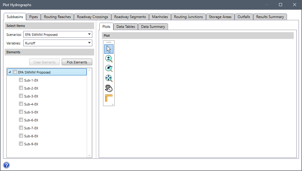
The above dialog box has separate panels (i.e., Subbasins, Pipes, Routing Reaches, Roadway Crossings etc.) to show output results for each element type present in the project. Within each element type panel, the user can select the preferred scenario from the Scenarios dropdown combo box of the Select Items panel.
The Variables dropdown combo box allows the user to select the desired output variables associated with an element type whose results are to be displayed.
Note that the Variables dropdown combo box is not available in the Result Summary panel. The Result Summary panel displays the summary of the current stormwater analysis results for each element in tabular form.
All elements (corresponding to the element type) present in the stormwater model of the selected scenario will be displayed under the Elements section. The user can check the checkbox corresponding to the preferred element(s) from the Elements section to see output results associated with them. Alternatively, the user can click the [Pick Elements] button to select the element(s) from the Map View. The user can click the [Clear Elements] button to clear the selected element(s). The output results related to the selected element(s) will be displayed under the Plots, Data Tables and Data Summary panels.