
Welcome to CivilGEO Knowledge Base
Welcome to CivilGEO Knowledge Base
For unsteady flow models, the HEC‑RAS Modified Puls Routing option can be used to define portions of a river reach that should be routed with the Modified Puls hydrologic routing method instead of the full St. Venant unsteady flow routing method. This option is very useful when encountering portions of the model that are very steep and the full unsteady flow routing method is either unstable or not feasible to use at all. This option only works as part of an unsteady flow analysis and is ignored when performing a steady flow analysis.
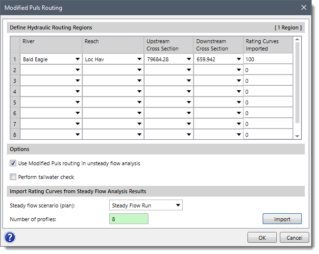
To display the Modified Puls Routing dialog box, select the Modified Puls Routing command from the Other Data dropdown menu of the Input ribbon menu.
To use the Modified Puls hydrologic routing option, the user must first create a steady flow model with the exact same geometry data. The purpose of the steady flow model is to compute a range of water surface profiles from very low to the highest expected flow rate. The results from the steady flow model are then used within the hydrologic routing reaches in order to provide the necessary discharge-volume data required by the Modified Puls hydrologic routing method.
Hydrologic routing reaches can be created almost anywhere in the model. A hydrologic routing reach must be at least two cross sections long. A hydrologic routing reach can be an upstream portion, downstream portion, or an intermediate portion of any existing HEC‑RAS unsteady flow river reach. The hydrologic routing reach can also encompass an entire HEC‑RAS river reach. Hydrologic routing reaches can contain roadway crossings (i.e., bridges and culverts) and lateral structures. However, it cannot contain an inline structure. If an inline structure is contained within a routing reach that is to be routed with the Modified Puls hydrologic routing method, then the hydrologic routing reach must stop at least two cross sections upstream of the inline structure. The hydrologic routing reach can then start immediately downstream of the inline structure.
The following data are defined in this dialog box.
This data table is used to define the starting and ending cross sections where the Modified Puls hydrologic routing method should be applied. The following columns are used to define this data.
This section defines the options to be used in the Modified Puls routing.
This section controls the importing of computed HEC‑RAS results (i.e., discharge vs. water surface elevation) for defining the hydrologic routing rating curve data.
Clicking the [Import] button causes the software to read in the computed discharge vs. water surface elevation data. This data is then stored as individual rating curve information at each cross section.
Note that the imported rating curve data for the Modified Puls routing is independent of the rating curve data defined in the Cross Section Data dialog box.


CivilGEO G2 Reviews
4.8/5.0 Rating, Over 230 Reviews

GeoHECRAS is recognized as the top Civil Engineering Design Software with an average of 4.8 out of 5.0 rating from over 230 real user reviews on G2.


We use cookies to give you the best online experience. By agreeing you accept the use of cookies in accordance with our cookie policy.
When you visit any web site, it may store or retrieve information on your browser, mostly in the form of cookies. Control your personal Cookie Services here.


