
Welcome to CivilGEO Knowledge Base
Welcome to CivilGEO Knowledge Base

The HEC‑RAS multiple opening computational method is a one‑dimensional flow approach to a complex hydraulic problem. This methodology has the following limitations:
In addition to the above limitations, HEC‑RAS restricts a multiple opening roadway crossing structure to a maximum of seven openings. If there are conveyance overflow areas at the roadway crossing, there can only be two conveyance type openings, located at the far left and right ends of the cross section.
Given these limitations, if you have a multiple opening crossing in which the water surface and energy vary significantly between openings, then the HEC‑RAS multiple opening computational method may not be the appropriate approach to use. An alternative to the multiple opening method is the divided flow method. This method is discussed below.
An alternative method for solving a multiple opening roadway crossing problem is to model the flow paths of each bridge opening as a separate river reach. This method is more time consuming and requires the user to have a greater understanding of how the flow will separate between openings. The benefit of using this method is that varying water surfaces and energies can be computed between openings. An example of a divided flow application is shown in the below figure.
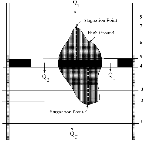
In the example shown in the above figure, high ground exists between the two openings (both upstream and downstream). Under low flow conditions, there are two separate and distinct channels. Under high flow conditions, the ground between the openings may be submerged, and the water surface is continuous across both openings.
To model this as a divided flow, the user must create two separate river reaches around the high ground and through the openings. Cross sections 2 through 8 must be divided at what the user believes is the appropriate stagnation points for each cross section. This can be accomplished in several ways. The cross sections could be physically split into two, or the user could use the same cross sections in both reaches. If the same cross sections are used, the user must block out the area of each cross section (using the ineffective flow option) that is not part of the flow path for that particular reach. In other words, if you were modeling the left flow path, you would block out everything to the right of the stagnation points. For the reach that represents the right flow path, everything to the left of the stagnation points would be blocked out.
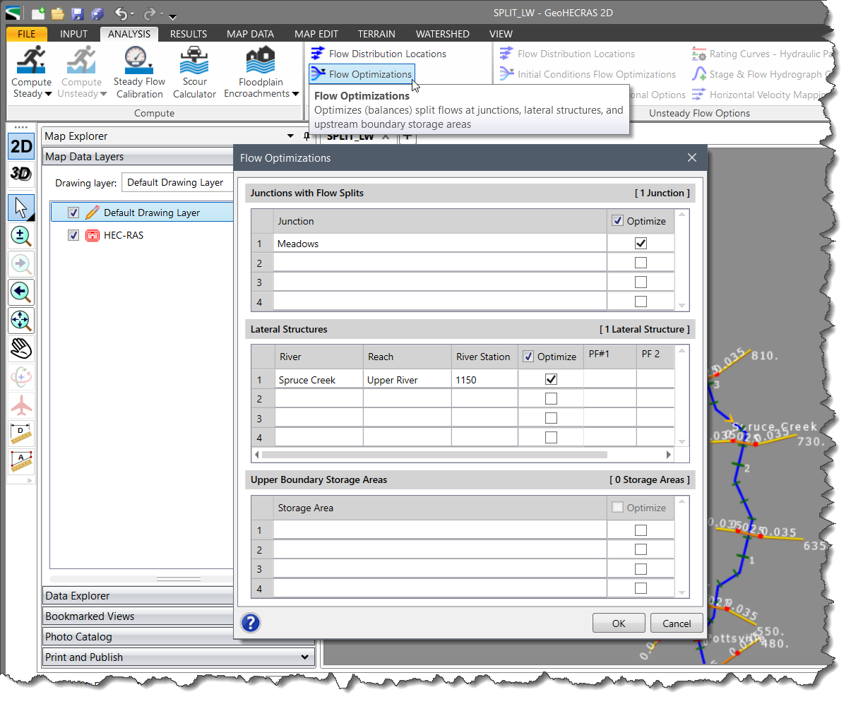
For modeling the divided flow, HEC‑RAS can optimize the flow split in order to determine how much flow is going through each reach. The user can provide an initial estimate of the flow distribution for each reach in the Steady Flow Data dialog box. Then, turning on the split flow optimization option in the Flow Optimizations dialog box, HEC‑RAS will use an iterative procedure to calculate the flow in each reach.


CivilGEO G2 Reviews
4.8/5.0 Rating, Over 230 Reviews

GeoHECRAS is recognized as the top Civil Engineering Design Software with an average of 4.8 out of 5.0 rating from over 230 real user reviews on G2.


We use cookies to give you the best online experience. By agreeing you accept the use of cookies in accordance with our cookie policy.
When you visit any web site, it may store or retrieve information on your browser, mostly in the form of cookies. Control your personal Cookie Services here.


