
Welcome to CivilGEO Knowledge Base
Welcome to CivilGEO Knowledge Base
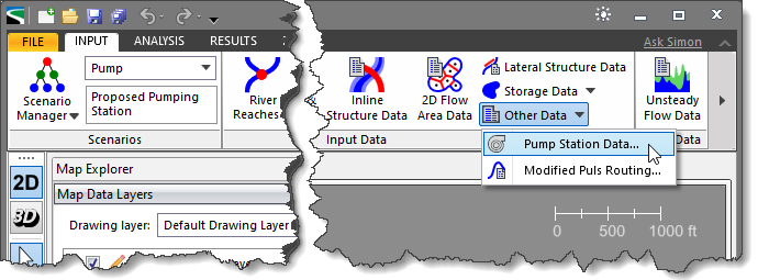
Pump stations are used to pump water from one location to another. In GeoHECRAS, the Pump Station Data command allows users to add pump stations and edit pump data in a project. Pump stations can be used to pump water between river reaches, storage areas, and 2D flow areas.
To define a pump station in a HEC-RAS project, follow the steps below:
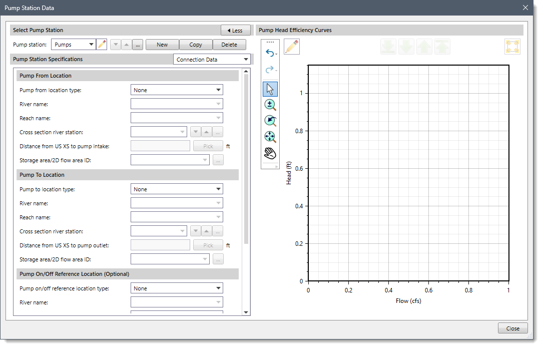
The following sections describe how to use the Pump Station Data command and interact with the above dialog box.
The Select Pump Station section allows the user to select, add, copy, and delete pump stations. To add a new pump station, click the [New] button and the dialog box will temporarily disappear. A prompt will be displayed on the status line, informing the user what to do next. Within the Map View, click on the location where you want to locate a pump station and the software will add a pump station at that location. The Pump Station Data dialog box will be redisplayed. Next, enter the pump station name in the Pump station entry and click the [Accept changes] button.
![[Accept changes] button](/wp-content/uploads/sites/25/2023/04/Pump-Station-Data-Imge-3.png)
To select an existing pump station from the Map View, click the […] button adjacent to the Pump station entry. The dialog box will temporarily disappear. Select the pump station on the Map View by clicking on it. The software will return to the dialog box. Alternatively, the user can select the pump station by double-clicking on the pump on the Map View, triggering the Pump Station Data dialog box to be displayed. Or the user can select the pump station from the Pump station dropdown combo box entry.
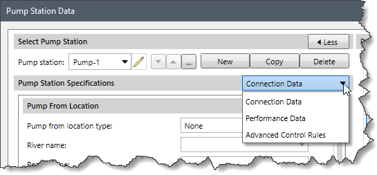
The following sections describe the pump station. Click on the dropdown selector at the Pump Station Specifications entry to display the various data panels that define the pump.
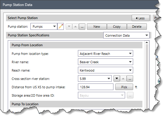
The Connection Data panel contains details about the pump connection, including where the water is being pumped from and to, the pump on/off reference location, and an optional maximum elevation set point along the pump line.
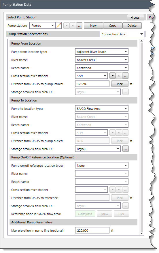
This section specifies the location where the pump station is pumping from. Select the source type from the Pump from location type dropdown combo box. Based on the selected type, additional data is used to define the source location.
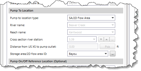
This section specifies the location where the pump station is pumping to. Select the target type from the Pump to location type dropdown combo box. Based upon the selected type, additional data is used to define the target location.
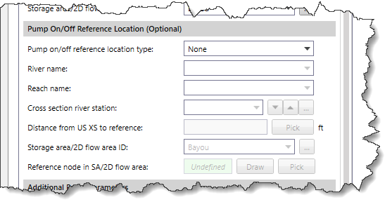
This section specifies the monitoring location that is used to determine when the pump should be on or off. The Pump on/off location type dropdown combo box can be used to select the reference type. Based upon the selected type, additional data is used to define the reference location.
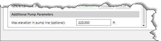
This section allows an optional highest elevation to be defined along the pump line. This is useful when defining a model where water is pumped over the top of a levee, and the water surface elevations of the Pump From and Pump To locations do not quantify the required head elevation to pump water over the top of a levee.
The Performance Data panel is used to define the pump performance curves for the defined pumps.
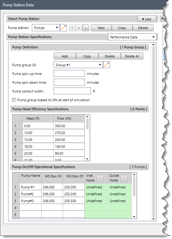
This section allows the user to define multiple pump groups, allowing similar pumps to be grouped together. In that way, the identification of sets of pumps and the specific control of them is more clearly defined.
Specify a group ID in the Pump group ID dropdown combo box. By default, the pump groups are named Group #1, Group #2, Group #3, etc., but can be changed by the user.
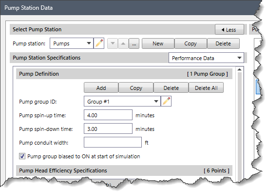
The Pump spin-up time and Pump spin-down time entries define the time required (in minutes) to turn a pump on and off. By default, pumps turn on and off instantly. In the real world, however, it takes some time for a pump to start up and shut down. In addition, if a pump abruptly turns on or off, a numerical shock in the flow computations might occur and the model may fail to converge to a valid solution. Therefore, it is recommended that a reasonable time-period be defined in which the pump transitions from zero flow to full capacity and transitions from full capacity to zero capacity.
The Pump group biased to ON at the start of simulation checkbox is used to default the selected pump group to an “On State” when the reference water surface is between the defined on/off elevations.
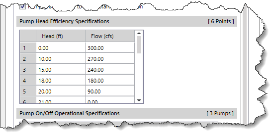
This section contains a table listing pump head versus flow rate. The pump head is the difference in water surface elevation between the Pump From and Pump To locations.
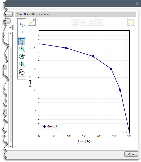
The user can visually inspect the pump performance graph showing flow rate and pump head in the Pump Head Efficiency Curves plot.
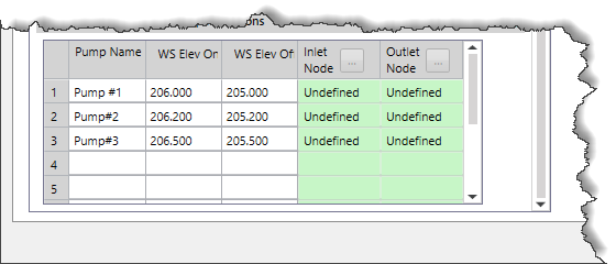
This section controls the operation of the defined pump. The provided table is used to specify the water surface elevations when a pump is to be turned on or off. Note that the defined pump on elevation (WS Elev On) must be higher than the defined pump off elevation (WS Elev Off).
The Advanced Control Rules panel is used to specify rules that override the previously defined pump performance and control data.
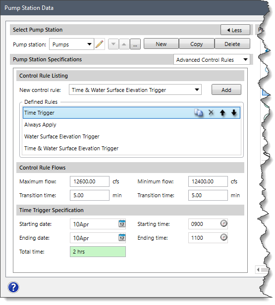
This section allows the user to define and set multiple rules for controlling the pumps. These rules are applied as per their listing order in the Defined Rules section. The user can reorder, copy, and delete rules. Depending upon the rule selected, different options are provided to specify the details of the selected rule.


CivilGEO G2 Reviews
4.8/5.0 Rating, Over 230 Reviews

GeoHECRAS is recognized as the top Civil Engineering Design Software with an average of 4.8 out of 5.0 rating from over 230 real user reviews on G2.


We use cookies to give you the best online experience. By agreeing you accept the use of cookies in accordance with our cookie policy.
When you visit any web site, it may store or retrieve information on your browser, mostly in the form of cookies. Control your personal Cookie Services here.


