
Welcome to CivilGEO Knowledge Base
Welcome to CivilGEO Knowledge Base
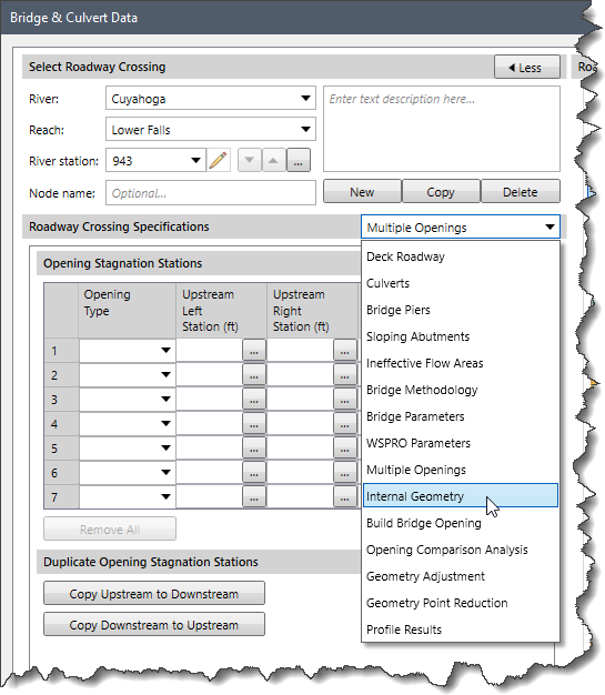
In GeoHECRAS, the Internal Geometry data panel of the Bridge & Culvert Data dialog box allows the user to edit the two-ground geometry cross sections inside of the bridge opening. This panel is used to change the station and elevation data, roughness coefficients, and main channel bank stations for each of the two internal bridge cross sections. This article describes how to use the Internal Geometry data panel.
Follow the steps below to use the Internal Geometry data panel:
The following sections describe how to interact with the Internal Geometry data panel of the Bridge & Culvert Data dialog box.
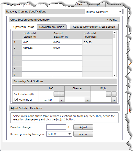
This section contains a tabbed header for Upstream Inside and Downstream Inside, corresponding to the two-ground geometry cross sections just inside of the bridge opening. These two cross sections are a copy of the ground geometry cross sections just upstream and downstream of the bridge. The provided table contains the horizontal station, elevation, and Manning’s roughness for these cross sections, and provides a means of editing this geometry. If the ground stations and/or elevations inside of the bridge structure are different than just outside of the bridge, then the internal bridge cross sections should be modified to reflect the change in geometry.
The table contains the following entries:
The user can copy the current interior opening geometry for the upstream cross section to the downstream cross section (or vice versa) by clicking on the [Copy to Downstream Cross Section] button.
This section defines the additional cross section geometry data.
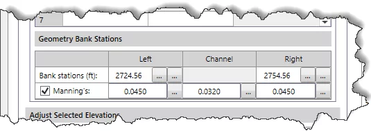
The Bank Stations field defines the left and right bank stations. The defined bank station must match an existing ground station. The user can click the […] pick buttons under the Left and Right entry fields to select the left and right bank stations from either Map View or the cross section plot.
The Manning’s checkbox entry defines Manning’s n roughness values for left overbank, channel, and right overbank. Clicking the […] lookup button displays a Manning’s roughness lookup table. Unchecking this checkbox entry disables the underlying fields and enables the Horizontal Roughness column under the Cross Section Ground Geometry data table.
This section allows the user to select rows in the above cross section ground geometry table for which elevations are to be adjusted. After selecting the desired rows, the user can define the elevation adjustment by clicking on the [Adjust] button to implement the elevation change.
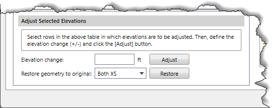
Clicking the [Restore] button allows the user to restore all of the internal cross section geometry data (stations and elevations data) for both upstream and downstream of the bridge to their original values.


CivilGEO G2 Reviews
4.8/5.0 Rating, Over 230 Reviews

GeoHECRAS is recognized as the top Civil Engineering Design Software with an average of 4.8 out of 5.0 rating from over 230 real user reviews on G2.


We use cookies to give you the best online experience. By agreeing you accept the use of cookies in accordance with our cookie policy.
When you visit any web site, it may store or retrieve information on your browser, mostly in the form of cookies. Control your personal Cookie Services here.


