
Welcome to CivilGEO Knowledge Base
Welcome to CivilGEO Knowledge Base
In GeoHECRAS, the Bridge Methodology data panel of the Bridge & Culvert Data dialog box allows the user to define which computational methods HEC-RAS will use at a bridge opening. This article describes how to use the Bridge Methodology data panel.
Follow the steps below to use the Bridge Methodology data panel:
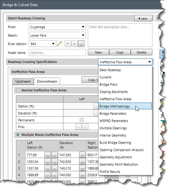
The following sections describe how to interact with the Bridge Methodology data panel of the Bridge & Culvert Data dialog box.
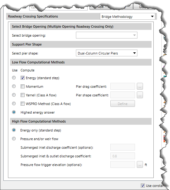
This section allows the user to choose the bridge opening types from the Select bridge opening dropdown box.
This section allows the user to select the bridge pier shape. By default, the Select pier shape dropdown combo box is set to Dual-Column Circular Piers for new bridges. The dropdown combo box lists the following options:
When importing a HEC-RAS model, the software will automatically set the pier shape by reviewing the defined pier drag coefficient value.
Based on the defined pier shape, the software will render the bridge pier to match. Circular piers, square piers, and triangular nose piers are roughly the same—just the leading (upstream) edge looks different.
This section allows the user to instruct HEC-RAS to use any or all of the low flow computational methods by selecting the checkboxes under the Compute label. If the Momentum and/or Yarnell methods are selected, the user must enter pier loss coefficients corresponding to each method.
The following table lists the drag coefficient for the different pier shapes.
| Pier Shape | Pier Drag Coefficient CD |
|---|---|
| Circular pier | 1.20 |
| Elongated piers with semi-circular ends | 1.33 |
| Elliptical piers with 2:1 length to width | 0.60 |
| Elliptical piers with 4:1 length to width | 0.32 |
| Elliptical piers with 8:1 length to width | 0.29 |
| Square nose piers | 2.00 |
| Triangular nose with 30° angle | 1.00 |
| Triangular nose with 60° angle | 1.39 |
| Triangular nose with 90° angle | 1.60 |
| Triangular nose with 120° angle | 1.72 |
The following table lists the Yarnell K coefficient for the different pier shapes.
| Pier Shape | Yarnell K Coefficient |
|---|---|
| Semi-circular nose and tail | 0.90 |
| Twin-cylinder piers with connecting diaphragm | 0.95 |
| Twin-cylinder piers without diaphragm | 1.05 |
| 90° angle triangular nose and tail | 1.05 |
| Square nose and tail | 1.25 |
| Ten pile trestle bent | 2.50 |
Once the user has selected the low flow bridge methods to be computed, the user must specify which methods will be used as the final answer to continue the computations upstream. Only one of the methods can be selected by choosing the corresponding radio button under the Use label to continue the computations upstream.
An alternative to selecting a single method is to instruct HEC-RAS to use the results with the highest computed upstream energy elevation. This is accomplished by selecting the Highest energy answer radio button option under the Use label. By default, the software selects the Highest energy answer radio button option.
This section allows the user to instruct HEC-RAS on how to compute high flows (flow at or above the maximum low chord elevation). For high flows, the user can choose between Energy only (Standard step) or Pressure and/or weir flow calculations.
If Pressure and/or weir flow is selected as the high flow method, the user must enter coefficients for the pressure flow equations. The first coefficient (Submerged inlet discharge coefficient) applies to the equation that is used when only the upstream side (inlet) of the bridge is submerged. If this coefficient is left blank, HEC-RAS selects a coefficient based on the amount of submergence. If the user enters a coefficient, that value is used for all degrees of submergence. The second coefficient (Submerged inlet & outlet discharge coefficient) applies to the equation that is used when both the upstream and downstream end of the bridge is submerged. By default, this coefficient is defined as 0.8.
The Pressure flow trigger elevation (optional) field is used to set the maximum elevation of the deck low chord and defines the elevation at which pressure flow calculations will begin. If this field is left blank, then the elevation that triggers pressure flow calculations is based on the highest low chord elevation on the upstream side of the bridge deck. If the user enters a value in this field, the entered value will be the trigger for pressure flow calculations to begin.
Pressure flow is triggered when the energy elevation exceeds the maximum low chord. When pressure flow is calculated, the answer is compared to the low flow answer, and the highest energy elevation of the two is selected. Alternatively, the user can tell the program to use the water surface elevation instead of the energy elevation to trigger pressure flow calculations.


CivilGEO G2 Reviews
4.8/5.0 Rating, Over 230 Reviews

GeoHECRAS is recognized as the top Civil Engineering Design Software with an average of 4.8 out of 5.0 rating from over 230 real user reviews on G2.


We use cookies to give you the best online experience. By agreeing you accept the use of cookies in accordance with our cookie policy.
When you visit any web site, it may store or retrieve information on your browser, mostly in the form of cookies. Control your personal Cookie Services here.


