
Welcome to CivilGEO Knowledge Base
Welcome to CivilGEO Knowledge Base
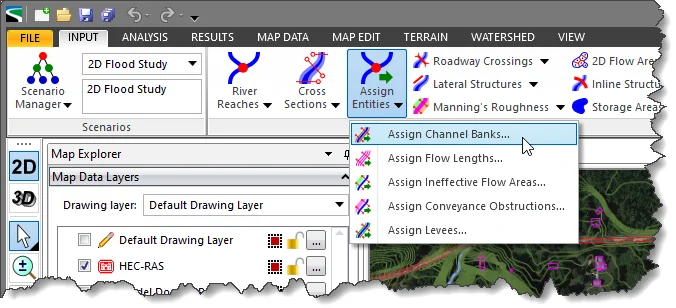
The Assign Channel Banks command of GeoHECRAS allows the user to assign channel bank locations using polylines or polygons, assumed channel normal flow depth, defined channel width, HEC-RAS computed water surface elevations for low flow conditions or end points of the cross sections.
Follow the steps below to use the Assign Channel Banks command:
The following sections describe how to use the Assign Channel Banks command and interact with the above dialog box.
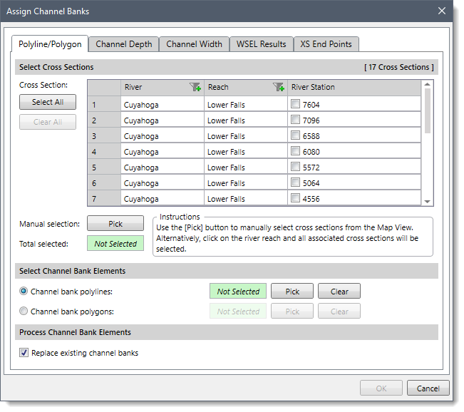
The Polyline/Polygon panel is used to assign the channel bank locations using polylines or polygons.
The Select Cross Sections section is used to manually select the cross sections for assigning channel bank locations. If a cross section is already selected on the Map View prior to running this command, the same cross section will be shown selected within the table.
Alternatively, the user can click the [Pick] button to interactively select the cross sections from the Map View. The user can also click on the river reach and all associated cross sections will be selected. Clicking the [Select All] button causes all the cross sections to be selected. The user can click the [Clear All] button to cancel the previous selection and redo the entire process.
In addition, the user can filter the specific river reaches to be shown in the table listing. Once the cross sections are selected, the number of selected cross sections will be displayed in the Total selected read only field.
The Select Channel Bank Elements section allows the user to select the polylines or polygons to be associated as channel banks. Click the [Pick] button to select the bank polylines or polygons from the Map View.
The software will first determine where the thalweg location is on the cross section. It will then move outward from the thalweg until a previously selected bank polyline or polygon edge is reached. The user can click the [Clear] button to cancel the previous selection and redo the entire process.
This section contains the Replace existing channel banks checkbox option. This option causes the software to replace already defined cross section channel banks for cross sections that are processed by defined channel bank polylines. This option is checked by default but will recall the user’s selection during the application session (i.e., if the user unchecks the option, it remains unchecked during that session of the application).
The Channel Depth panel is used to assign the channel bank locations at the cross sections using assumed channel normal flow depth.
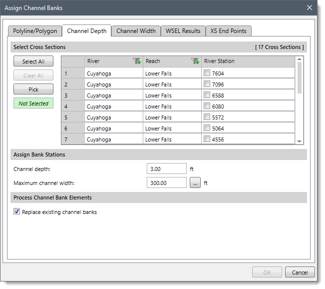
The Select Cross Sections section allows the user to manually select the cross sections for assigning channel bank locations.
The Assign Bank Stations section allows the user to define the channel depth and maximum channel width to construct channel bank locations. The user can enter a channel depth value in the Channel depth entry field and channel width value in the Maximum channel width entry field. By default, the software uses a value of 3 ft for the Channel depth and 300 ft for the Maximum channel width. The user can enter different values. Clicking the […] button allows the user to measure the maximum channel width from the map view.
The software will first determine where the thalweg location is on the cross section. It will then move outward from the thalweg until the requested channel depth is reached within the maximum channel width specified.
This section allows the user to replace already defined cross section channel banks for cross sections that are processed by defined channel bank polylines.
The Channel Width panel is used to assign the channel bank locations at the cross sections using a defined channel width.
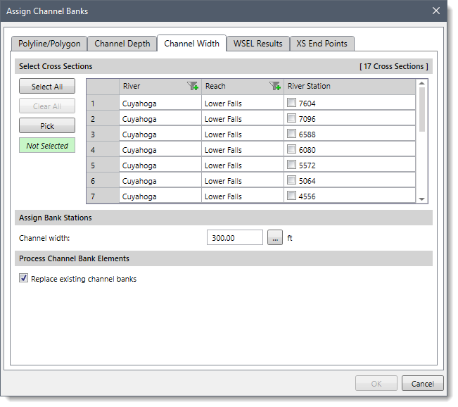
The Select Cross Sections section allows the user to manually select the cross sections for assigning channel bank locations.
The Assign Bank Stations section allows the user to define a maximum channel width for assigning channel bank locations. The user can enter a maximum channel width value in the Channel width entry field. By default, the software uses a value of 300 ft for the Channel width. The user can enter a different value or click the […] button to measure the maximum channel width from the Map View.
The software will first determine where the thalweg location is on the cross section. It will then move outward from the thalweg equally until the requested channel width is reached.
This section allows the user to replace already defined cross section channel banks for cross sections that are processed by defined channel bank polylines.
The WSEL Results panel is used to assign channel bank locations using the computed water surface elevations for low flow conditions.
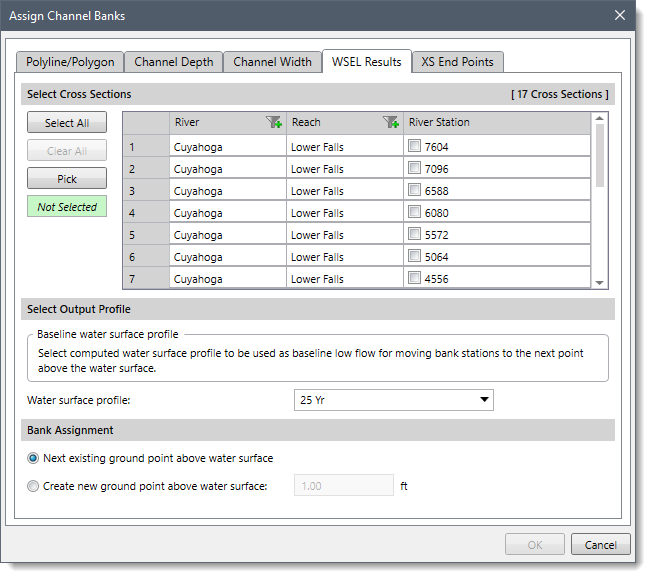
The Select Cross Sections section allows the user to manually select the cross sections for assigning channel bank locations.
The Select Output Profile section is used to select the computed water surface profile to be used as baseline low flow and then move channel bank locations to the next point above the water surface. From the Water surface profile dropdown combo box, the user can select the water surface profile. By default, the Maximum WSEL option is selected.
The Bank Assignment section provides the following options to construct channel bank locations:
The XS End Points panel is used to assign the channel bank locations at the end points of the cross sections.
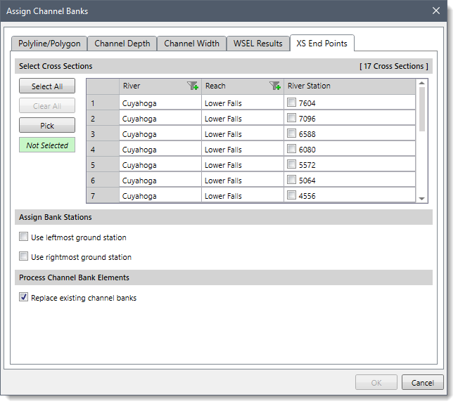
The Select Cross Sections section allows the user to manually select cross sections for assigning channel bank locations.
The Assign Bank Stations section provides the following options to construct channel bank locations:
This section allows the user to replace already defined cross section channel banks for cross sections that are processed by defined channel bank polylines.
When the data have been defined in the Assign Channel Banks dialog box, click the [OK] button. The software will then look at each selected option and assign the channel bank locations.


CivilGEO G2 Reviews
4.8/5.0 Rating, Over 230 Reviews

GeoHECRAS is recognized as the top Civil Engineering Design Software with an average of 4.8 out of 5.0 rating from over 230 real user reviews on G2.


We use cookies to give you the best online experience. By agreeing you accept the use of cookies in accordance with our cookie policy.
When you visit any web site, it may store or retrieve information on your browser, mostly in the form of cookies. Control your personal Cookie Services here.


