In GeoSTORM, the Storage Area Data command allows the user to define storage area data and view the corresponding output results associated with the storage areas.
Follow the steps below to define the data associated with the storage areas using the Storage Area Data command:
- From the Input ribbon menu, click the Storage Areas dropdown menu and select the Storage Area Data command. Alternatively, the user can double-click on the storage area from the Map View.

- The Storage Area Data dialog box will be displayed, as shown below.
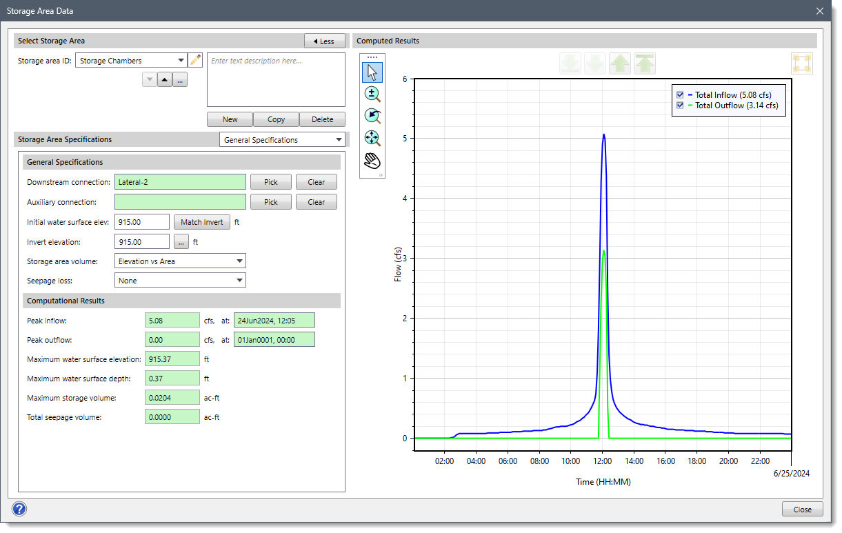
The following sections describe how to define data in the Storage Area Data command and interact with the above dialog box.
Selecting Storage Area
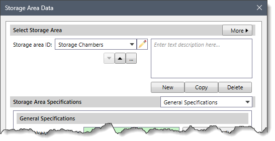
The Select Storage Area section allows the user to:
- Create new storage areas.
- Copy data from an existing storage area to a new storage area.
- Delete existing storage areas.
- Navigate between the existing storage areas, etc.
The following entries are provided in this section:
- Storage area ID
This dropdown combo box lists all the storage areas defined in the current scenario of the project. Click on the edit option (i.e., the pencil icon) to edit the storage area ID. The user can navigate between the available storage areas using the Up and Down arrow buttons. Alternatively, the user can click the […] button to select the storage area from the Map View.
Note that the Up and Down arrow buttons will be disabled (i.e., grayed out) if the current scenario of the project contains only one storage area.
- Description
This optional textbox field allows the user to enter additional information that describes the selected storage area.
- New
The [New] button allows the user to draw a new storage area on the Map View. Every newly created storage area is automatically assigned a unique ID, which is editable.
- Copy
The [Copy] button allows the user to create a copy of the selected storage area on the Map View along with its associated data. The software automatically provides a unique ID to the copied storage area.
- Delete
The [Delete] button allows the user to delete the selected storage area from the current scenario.
- Less/More
The [< Less] and [More >] buttons at the Select Storage Area section header allow the user to expand or collapse the Computed Results plot section.
Note that the [< Less] and [More >] buttons are not available when the Rational Method is selected as the hydrology analysis engine in the Scenario Manager dialog box. This is because, for the Rational Method, there is no concept of time and hence no concept of routing flows as the analysis assumes steady-state peak flows at all nodes.
Storage Area Specifications
The Storage Area Specifications dropdown combo box contains several data panel entries that allow the user to define storage area data. The following data panel entries are listed in the dropdown combo box:
- General Specifications
- Additional Inflows
- Discharge Rating Curve
- Pump Outflow
- Riser Outflow Pipe
- Riser Outflow Structure
- Storage Area Culvert
- Storage Area Seepage
- Storage Area Spillways
- Storage Area Volume
- Underground Pipe Gallery
- Underground Storage Chamber

General Specifications
This panel allows the user to define general parameters and view the stormwater computational results for the selected storage area.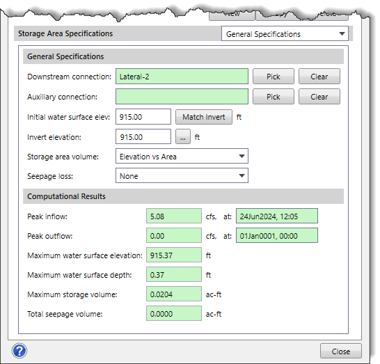
General Specifications
The following entries are provided in this section:
- Downstream connection
This entry field defines the downstream connection element that the selected storage area drains to such as the manhole, routing junction, and storage area. The read-only field next to this entry displays the element ID of the downstream connection. The user can click the [Pick] button to select the downstream connection element from the Map View. Clicking the [Clear] button allows the user to remove the selected downstream connection.
- Auxiliary connection
This optional entry field defines the downstream auxiliary connection element that the selected storage area drains to such as the manhole, routing junction, and storage area. The read-only field next to this entry displays the element ID of the auxiliary connection. The user can click the [Pick] button to select the downstream element from the Map View. Clicking the [Clear] button allows the user to remove the auxiliary connection.
Note that all storage areas have a main (or primary) discharge to a downstream element. Flow through outlets, spillways, and other structures leave the storage area and enter downstream channels. However, some storage areas also have a separate auxiliary (or secondary) discharge locations in addition to the main discharge location. This auxiliary discharge connection does not flow into the same channel as the main discharge. Instead, it may be an emergency spillway that enters a secondary channel that eventually enters the main downstream channel. The auxiliary discharge could also be a withdrawal for urban consumptive use or an irrigation canal.
- Initial water surface elev
This entry field defines the water surface elevation of the storage area at the start of the analysis. The user can click the [Match Invert] button to retrieve the minimum elevation from the Storage -Area/Storage-Volume curve data.
- Invert elevation
This entry field defines the invert elevation of the storage area. The user can click the […] button to select the invert elevation from the Map View.
- Storage area volume
This dropdown combo box allows the user to select the type of volume data that is to be defined for the storage area. The following storage area volume types are available:
- Cylindrical Chamber
- Depth vs Area
- Elevation vs Area
- Rectangular Chamber
- Underground Pipe Gallery
- Underground Storage Chamber

- Seepage loss
This dropdown combo box allows the user to select the type of seepage data that is to be defined for the storage area. The following seepage loss types are available:
- None
- Green Ampt
Additional Inflows
This panel allows the user to specify the time history of direct external inflows entering the storage area being defined. These inflows are represented by both a constant and a time-varying component. The additional inflows are added directly to the storage area and can be used for flow routing in the absence of any runoff computations (as in a study area where no subbasins are defined). In river or stream modeling, user-defined inflows can be used to define the baseflow.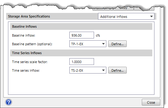
Baseline Inflows
The following entries are provided in this section:
- Baseline inflow
This entry field allows the user to define a constant baseline inflow. If this field is left blank, then no baseline inflow is assumed.
- Baseline pattern (optional)
This dropdown combo box allows the user to select an optional time pattern defined in the current scenario whose factors adjust the baseline inflow. If this dropdown list is left blank, then the baseline inflow will not be adjusted.
Clicking the [Define] button displays the Time Patterns Data dialog box, which allows the user to define a specific pattern to be applied to the defined Baseline Inflow. Refer to this article in our knowledge base to learn more about the Time Patterns Data dialog box.
Time Series Inflows
The following entries are provided in this section:
- Time series scale factor
This entry field allows the user to define a multiplier to adjust the values of the inflow time series.
- Time series inflow
This dropdown combo box allows the user to select the time series inflow defined in the current scenario. If None is selected, no time series inflow will be assigned to the storage area.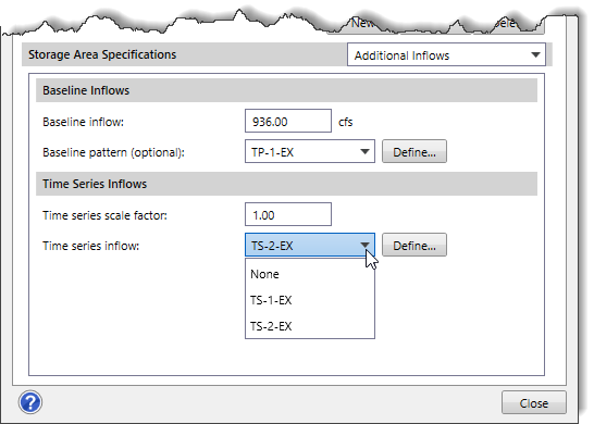
Clicking the [Define] button displays the Time Series Data dialog box, which allows the user to define a specific time series inflow data set to be used. Refer to this article in our knowledge base to learn more about the Time Series Data dialog box.
Discharge Rating Curve
This panel allows the user to define the complete relationship relating to how storage area discharges flow to the downstream node such as a manhole, routing junction, or another storage area.
Discharge Rating Curve Routing
Auxiliary Connection
The Auxiliary connection checkbox option allows the software to connect the storage area to the auxiliary connection element rather than to the downstream connection element (i.e., manhole, routing junction, or storage area). The read-only field next to this checkbox option displays the element ID of the auxiliary connection. Note that this checkbox option is disabled (i.e., grayed out) if there is no auxiliary connection element defined for the selected storage area. By default, this checkbox option is unchecked.
Routing Reference Method
The Routing reference method dropdown combo box allows the user to define how the software is to route water from the storage area to the next downstream element such as a manhole, routing junction, or another storage area. The following routing reference methods are available:
- None
- Head Differential
- Water Surface Depth
- Water Surface Elevation
Rating Curve Data
This subpanel displays a data grid that defines the rating curve parameters corresponding to the method selected in the Routing reference method dropdown combo box.
The following columns are provided in this data grid:
- Water Surface Depth
This column defines the water surface depth that is used to construct the discharge rating curve. Note that this column header name changes based upon the routing reference method selected, as shown in the below table.
Routing Reference Method Column 1 Column 2 Head Differential Head Differential Flow Rate Water Surface Depth Water Surface Depth Flow Rate Water Surface Elevation Water Surface Elevation Flow Rate - Flow Rate
This column references the flow rate that is used to construct the discharge rating curve.
Rating Curve Plot
This subpanel displays a graphical plot corresponding to the data defined in the Rating Curve Data subpanel.
Pump Outflow
This panel allows the user to define the pump outflow parameters for the storage area. Refer to this article in our knowledge base to learn more about the Pump Outflow panel.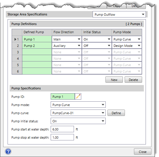
Riser Outflow Pipe
This panel allows the user to define the general parameters for the pipe that directly discharges the flow captured by the vertical riser structure. Refer to this article in our knowledge base to learn more about the Riser Outflow Pipe panel.
Riser Outflow Structure
This panel allows the user to define the following parameters: the dimensions of the riser outflow structure and horizontal orifices associated with it, and weirs embedded into the structure. Refer to this article in our knowledge base to learn more about the Riser Outflow Structure panel.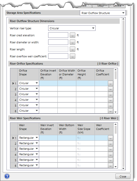
Storage Area Culvert
This panel allows the user to define the culvert that directly discharges from the storage area to the downstream element such as a manhole, routing junction, or another storage area without going through a vertical riser structure. Refer to this article in our knowledge base to learn more about the Storage Area Culvert panel.
Storage Area Seepage
This panel allows the user to define the seepage parameters for the storage area. Note that this panel is enabled only when Green Ampt is selected in the Seepage loss dropdown combo box of the General Specifications panel. Otherwise, this data panel entry is disabled (i.e., grayed out).
Seepage Definition
The following entries are provided in this section:
- Suction head
This entry field defines the average value of soil capillary suction along the wetting front. Clicking the […] button displays the Soil Characteristics lookup dialog box, which allows the user to choose the suction head value to be assigned to a storage area.
- Hydraulic conductivity
This entry field defines hydraulic conductivity of the underlying soil. Clicking the […] button displays the Soil Characteristics lookup dialog box, which allows the user to choose the hydraulic conductivity value to be assigned to a storage area.
- Initial deficit
This entry field defines the initial deficit of the underlying soil.
Storage Area Spillways
This panel allows the user to define a spillway that directly discharges from the storage area to the downstream element such as a manhole, routing junction, or another storage area without going through a vertical riser structure. Refer to this article in our knowledge base to learn more about the Storage Area Spillways panel.
Storage Area Volume
This panel allows the user to define the volume data for the selected storage area. Note that this panel changes based upon the selected storage area volume types in the Storage area volume dropdown combo box of the General Specifications panel. Refer to this article in our knowledge base to learn more about the Storage Area Volume panel.
Underground Pipe Gallery
This panel allows the user to define the underground pipe gallery. Note that this panel is enabled only when Underground Pipe Gallery is selected in the Storage area volume dropdown combo box of the General Specifications panel. Otherwise, this data panel entry is disabled (i.e., grayed out). Refer to this article in our knowledge base to learn more about the Underground Pipe Gallery panel.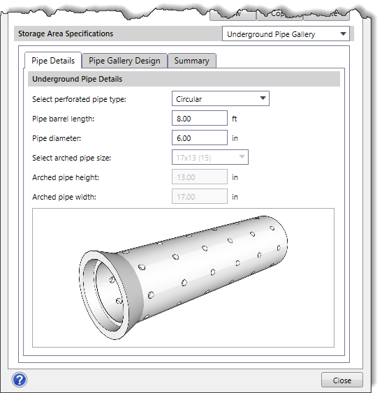
Underground Storage Chamber
This panel allows the user to define the underground storage chamber. Note that this panel is enabled only when Underground Storage Chamber is selected in the Storage area volume dropdown combo box of the General Specifications panel. Otherwise, this data panel entry is disabled (i.e., grayed out). Refer to this article in our knowledge base to learn more about the Underground Storage Chamber panel.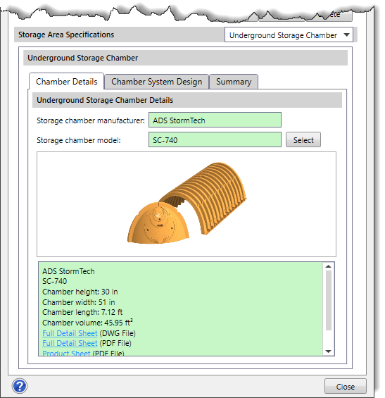
Computational Results
After successfully computing the analysis, this section provides a summary of the stormwater computational results for the selected storage area.
The following results are provided in this section:
- Peak inflow
This read-only field displays the peak flow rate that entered the storage area during the storm event.
- Peak outflow
This read-only field displays the peak flow rate that leaves the storage area during the storm event.
- Maximum water surface elevation
This read-only field displays the maximum water surface elevation at the storage area during the storm event.
- Maximum water surface depth
This read-only field displays the maximum water surface depth at the storage area during the storm event.
- Maximum storage volume
This read-only field displays the maximum storage volume at the storage area during the storm event.
- Total seepage volume
This read-only field displays the total water that has seeped out of the storage area during the entire storm event.