The Storage Area Culvert panel of the Storage Area Data dialog box allows the user to define general parameters for the culvert that directly discharges from the storage area to the downstream element (i.e., manhole, routing junction, storage area, etc.) without going through a vertical riser structure. This article describes how to interact with the Storage Area Culvert panel. Refer to this article in our knowledge base to learn more about the Storage Area Data dialog box.
Follow the steps below to define the specifications for the storage area culvert:
- In the Storage Area Data dialog box, select Storage Area Culvert from the Storage Area Specifications dropdown combo box.
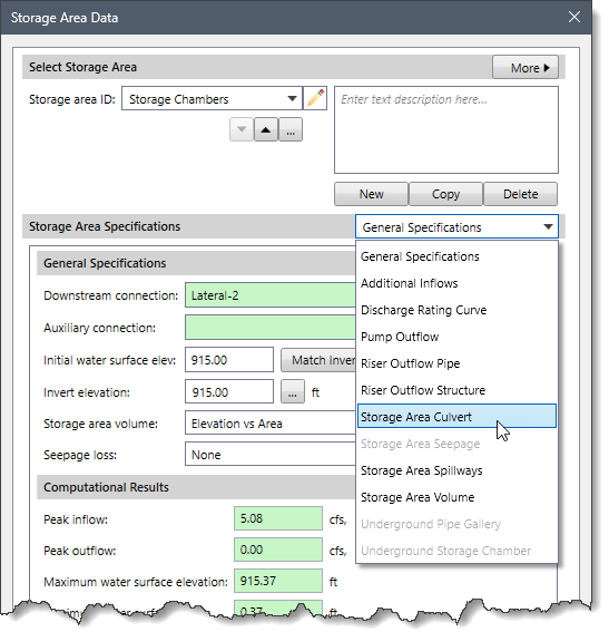
- The corresponding panel with options for defining the culvert will be displayed.

Culvert Definition
This section allows the user to define the general parameters for the selected culvert.
The following parameters are provided in this section:
- Culvert shape
This dropdown combo box allows the user to select the type of culvert shape. The following culvert shapes are available:
- Arch
- Box
- Circular
- Ellipse
- Pipe Arch

- Backflow flap gate
This checkbox option specifies whether a flap gate will be enabled to prevent backflow (or flow reversal) for the culvert. By default, this checkbox option is unchecked.
- Culvert type
This dropdown combo box lists the available culvert types that are supported. Note that the options in the dropdown combo box will change based on the selected culvert shape.
- Culvert entrance
This dropdown combo box lists the available culvert entrance types that are supported. Note that the options in the dropdown combo box will change based on the selected culvert shape.
- Number barrels
This spin-control entry defines the number of identical culvert barrels that are defined. By default, the software uses a value of 1. However, the user can enter a value ranging from 1 to 10.
- Discharge to downstream auxiliary connection
This checkbox option allows the software to connect the culvert to the auxiliary connection element rather than to the downstream connection element (i.e., manhole, routing junction, or storage area). The read-only field next to this checkbox option displays the element ID of the auxiliary connection. Note that this checkbox option is disabled (i.e., grayed out) if there is no auxiliary connection element defined for the selected storage area. By default, this checkbox option is unchecked.
Culvert Dimensions
This section allows the user to define the dimensions and other parameters of the culvert.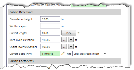
The following parameters are provided in this section:
- Diameter or height
This entry field defines the diameter of a circular culvert or the height of a box culvert.
- Width or span
This entry field defines the width (or span) of a box culvert. Note that this entry field is only available when Box is selected as the culvert shape in the Culvert Definition section. Otherwise, this entry field is disabled (i.e., grayed out).
- Culvert length
This entry field defines the length of the culvert being modeled. The user can click the [Pick] button to measure the culvert length from the Map View.
- Inlet invert elevation
This entry field defines the culvert invert elevations on the upstream (inlet) end. The user can click the […] button to select the culvert inlet invert elevation from the Map View. Clicking the [Down] arrow button causes the culvert invert elevation to be set equal to the storage area invert elevation.
- Outlet invert elevation
This entry field defines the culvert invert elevations at the downstream (outlet) end. The user can click the […] button to select the culvert outlet invert elevation from the Map View. Clicking the [Down] arrow button causes the culvert invert elevation to be set equal to the storage area invert elevation.
- Culvert slope (H:V)
This entry field displays the slope of the culvert. In addition, this field can be used to set the slope of the culvert. The user can click on the edit option (i.e., the pencil icon) adjacent to the Culvert slope (H:V) field to change the read-only field into an editable field. The user can then enter the culvert slope and click on the [Accept changes] button. The software will then adjust the unlocked culvert end invert elevation to meet the updated slope value.![Culvert slope (H:V) entry - [Accept changes] button](https://knowledge.civilgeo.com/wp-content/uploads/2024/12/Defining-Storage-Area-Culvert-Image-7-1.png)
Note: To set the slope of the culvert, the user should first select the end of the culvert invert elevation that is to be locked. The following options are provided in the dropdown combo box adjacent to the Culvert slope (H:V) entry field:
- Lock Downstream Invert
- Lock Upstream Invert
Culvert Coefficients
This section allows the user to define Manning’s roughness, entrance loss and exit loss coefficients for the selected culvert.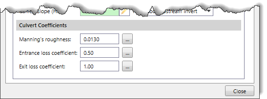
The following parameters are provided in this section:
- Manning’s roughness
This entry field defines the roughness of the pipe being used as a culvert. Clicking the […] button displays the Manning’s Roughness lookup dialog box, which allows the user to choose a Manning’s roughness coefficient to be assigned to a culvert.
- Entrance loss coefficient
This entry field defines the head loss coefficient associated with energy losses at the inlet of the pipe as the flow enters the pipe from a node (i.e., manhole, junction box, routing junction, catch basin, or storage area). Clicking the […] button displays the Culvert Entrance Loss Coefficients lookup dialog box, which allows the user to choose the entrance loss coefficient to be assigned to a culvert.
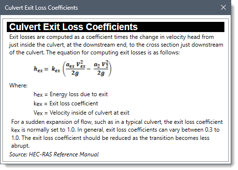
- Exit loss coefficient
This entry field defines the head loss coefficient associated with energy losses at the outlet of the pipe as the flow leaves the pipe and enters a node (i.e., manhole, junction box, routing junction, catch basin, or storage area). Clicking the […] button displays the Culvert Exit Loss Coefficients lookup dialog box, which allows the user to choose the exit loss coefficient to be assigned to a culvert.