The Underground Pipe Gallery panel of the Storage Area Data dialog box allows the user to define the underground pipe gallery specifications for the storage area. This article describes how to interact with the Underground Pipe Gallery panel. Refer to this article in our knowledge base to learn more about the Storage Area Data dialog box.
Follow the steps below to define the specifications for the underground pipe gallery:
- In the Storage Area Data dialog box, select Underground Pipe Gallery from the Storage Area Specifications dropdown combo box.
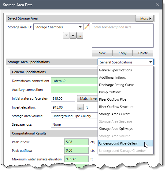
Note: The Underground Pipe Gallery data panel entry is enabled only when the user selects the Underground Pipe Gallery option in the Storage area volume dropdown combo box of the General Specifications panel. Otherwise, this data panel entry is disabled (i.e., grayed out).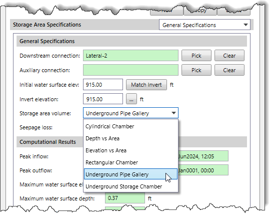
- The corresponding panel with options for defining the underground pipe gallery will be displayed.

The following subpanels are available in the Underground Pipe Gallery data panel:
- Pipe Details
- Pipe Gallery Design
- Summary
Pipe Details
In the Pipe Details subpanel, the Underground Pipe Details section allows the user to define the underground pipe parameters for the selected storage area.
The following entries are available:
- Select perforated pipe type
This dropdown combo box allows the user to select the type of perforated pipe. The following types of perforated pipes are available:
- Arched Flat Bottom
- Arched Round Bottom
- Circular
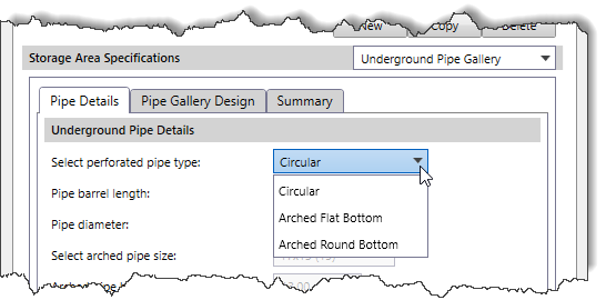
- Pipe barrel length
This entry field defines the length of individual pipe barrels.
- Pipe diameter
This entry field defines the diameter of the pipe to be used in the pipe runs. Note that this field is enabled only for the Circular pipe type.
- Select arched pipe size
This dropdown combo box allows the user to select the size of the arched pipe. Note that this dropdown combo box is enabled only for the Arched Round Bottom pipe type.
- Arched pipe height
This entry field defines the height of the arched pipe to be used in the pipe runs. Note that this field is enabled only for the Arched Flat Bottom pipe type. Otherwise, this field is disabled (i.e., grayed out) for the Circular pipe type and becomes read-only for the Arched Round Bottom pipe type.
- Arched pipe width
This entry field defines the width of the arched pipe to be used in the pipe runs. Note that this field is enabled only for the Arched Flat Bottom pipe type. Otherwise, this field is disabled (i.e., grayed out) for the Circular pipe type and becomes read-only for the Arched Round Bottom pipe type.
Pipe Gallery Design
In the Pipe Gallery Design subpanel, the Pipe Gallery Specifications and Layout section allows the user to define the specifications and layout of the pipe gallery system.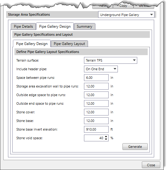
The following tab panels are available in the Pipe Gallery Design subpanel:
- Pipe Gallery Design
- Pipe Gallery Layout
Pipe Gallery Design
In the Pipe Gallery Design tab panel, the Define Pipe Gallery Layout Specifications section allows the user to define the parameters for the pipe gallery layout.
The following entries are available:
- Terrain surface
This dropdown combo box allows the user to select the terrain elevation surface available in the project.
- Include header pipe
This dropdown combo box allows the user to specify how the header pipe is connected to the parallel pipe runs. The following options are available:
- None
- On One End
- On Both Ends

- Space between pipe runs
This entry field defines the gap between pipe runs so that stone fill can be inserted.
- Storage area excavation wall to pipe runs
This entry field defines the buffer distance provided from the storage area boundary to the pipe runs. Note that pipes can only be placed inside this buffer region.
- Outside edge space to pipe runs
This entry field defines the extra space that is placed on the pipe run outside the edge perimeter for stone fill.
- Outside end space to pipe runs
This entry field defines the extra space that is placed on the pipe run outside the end perimeter for stone fill.
- Stone cover
This entry field defines the stone cover to be placed over the pipe runs.
- Stone base
This entry field defines the stone base to be placed under the pipe runs.
- Stone base invert elevation
This entry field defines the invert elevation of the stone base.
- Stone void space
This spin control entry field defines the stone void space, represented as a percentage. By default, the software uses a value of 40. However, the user can enter a different value ranging from 10 to 90.
Once all required data have been defined, click the [Generate] button. The software generates the pipe gallery layout and immediately takes the user to the Pipe Gallery Layout tab panel.
Note: The [Generate] button is enabled only when all required data have been defined in the Pipe Gallery Design tab panel. Otherwise, this button will be disabled (i.e., grayed out).
Pipe Gallery Layout
The Pipe Gallery Layout tab panel displays a preview of the pipe gallery created on the Map View. Initially, the preview shows the current Map View extents, but the user can zoom and pan this view using the mouse cursor.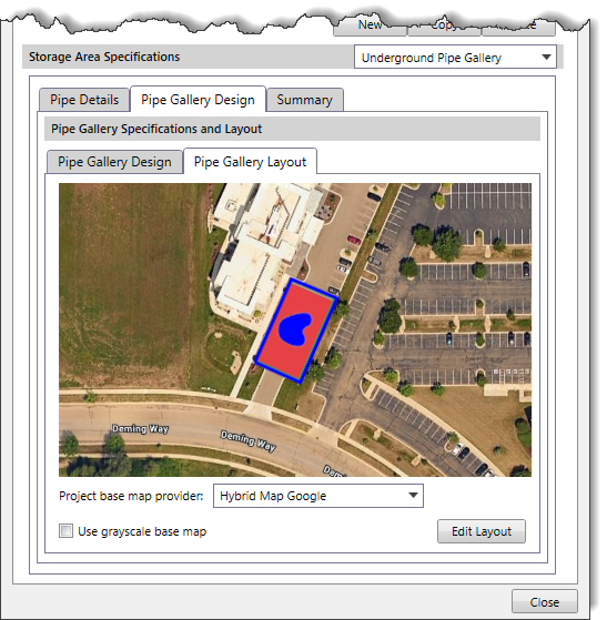
The following entries are available:
- Project base map provider
This dropdown combo box allows the user to select the project base map from several high-quality base maps.
- Use grayscale base map
This checkbox option allows the user to change the base map to grayscale instead of color.
Editing Pipe Gallery Layout
Clicking the [Edit Layout] button temporarily disappears the Storage Area Data dialog box and displays the Edit Layout dialog box. This dialog box allows the user to adjust the pipe gallery layout more precisely. In this dialog box, the user can define the pipe gallery boundary and manually add or remove pipes. After making the necessary changes, click the [OK] button to save the layout. The Storage Area Data dialog box will be redisplayed, and the Pipe Gallery Layout preview tab will be updated with the changes made. To abort the process, click the [Cancel] button.
The Edit Layout dialog box provides the following toolbar commands for editing the pipe gallery layout:
| Toolbar Command Icon | Toolbar Command | Description |
|---|---|---|
 | Move & Rotate Pipe Gallery Layout Grid | This command moves and rotates the layout grid along with the pipes. |
 | Move & Rotate Storage Chamber Boundary | This command moves and rotates the boundary of the storage chamber. |
 | Edit Storage Chamber Boundary | This command edits the vertices of the storage chamber boundary. |
 | Move Pipe within Pipe Gallery Layout Grid | This command moves selected pipes within the pipe gallery layout grid. |
 | Add Pipe to the Pipe Gallery Layout Grid | This command adds a new pipe to the pipe gallery layout grid. |
 | Add Pipe Header to the Pipe Gallery Layout Grid | This command adds a pipe header to the pipe gallery layout grid. |
 | Remove Pipe and/or Header from the Pipe Gallery Layout Grid | This command removes the pipe/header from the pipe gallery layout grid. |
 | Flip Pipe Header to the other end of the Pipe Gallery Layout Grid | This command flips the pipe header from top to bottom or bottom to top within the pipe gallery layout grid. |
 | Measure Distance | This command measures the distance on the pipe gallery layout view by drawing a temporary polyline. |
 | Toggle display of Base Map | This command shows or hides the base map layer in the Map View. |
In addition, the user can zoom and pan the pipe gallery layout grid in the Map View. Refer to this article in our knowledge base to learn more about the other tools available in this dialog box.
Summary
The Summary subpanel provides a volume summary for the pipe gallery system, including the depth-area-volume plot and corresponding data in a tabular format.
The following tab panels are available in the Summary subpanel:
- Volume Summary
- Depth-Area Volume Plot
- Data Table
Volume Summary
In the Volume Summary tab panel, the Pipe Gallery Volume Summary section displays the volume summary for the pipe gallery system. Note that this section is populated only when the user has generated the pipe gallery layout in the Pipe Gallery Design subpanel.
The following entries are available:
- Total number of pipe barrels
This read-only field displays the total pipe barrels placed in the pipe gallery system.
- System footprint area (including buffer)
This read-only field displays the footprint area of the pipe gallery system, which is equal to the area of the buffer polygon.
- Total excavation volume (including buffer & cover)
This read-only field displays the volume of the earthwork to be excavated for the pipe gallery system, including exterior buffer and ground cover.
- Total ground cover volume
This read-only field displays the volume of excavation required for providing the ground cover to the pipe gallery system.
- Total pipe gallery volume (without stone fill)
This read-only field displays the total storage volume of the pipe gallery.
- Total stone fill required (includes void space)
This read-only field displays the storage volume of the stone fill (including void space).
- Stone void volume
This read-only field displays the storage volume provided by the voids of the stone fill.
- Total gallery storage volume (pipe & stone void space)
This read-only field displays the total storage volume defined by the pipe gallery system. This volume includes the storage volume of the pipe gallery and the stone fill voids.
Clicking the [Calc] button computes the volume summary for the pipe gallery system. Note that the [Calc] button is enabled only when changes are made in the pipe gallery layout using the Edit Layout dialog box. Otherwise, this button is disabled (i.e., grayed out).
Clicking the [Pipe Gallery Report] button displays the Pipe Gallery Report dialog box, which allows the user to generate a report of the pipe gallery system in Microsoft Word or PDF format. Refer to this article in our knowledge base to learn more about the Pipe Gallery Report dialog box.
Depth-Area-Volume Plot
In the Depth-Area-Volume Plot tab panel, the Pipe Gallery Depth-Area-Volume Plot section displays the depth-area-volume plot of the pipe gallery system based on the computed volume summary from the Volume Summary tab panel.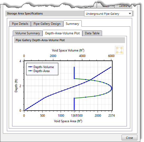
Data Table
In the Data Table tab panel, the Pipe Gallery Depth-Area-Volume Data Table section displays the depth vs. area and volume data in a tabular format, based on the computed volume summary from the Volume Summary tab panel.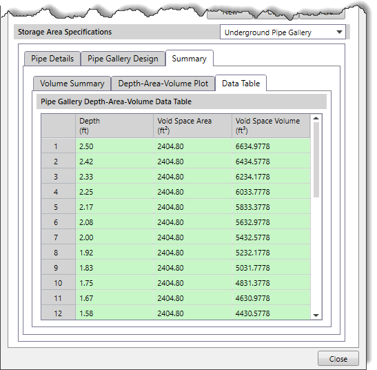
The following read-only columns are available in the Pipe Gallery Depth-Area-Volume Data Table section:
- Depth
This read-only column lists the cumulative depth value of the pipe gallery system.
- Void Space Area
This read-only column lists the cumulative value of the void space area of the pipe gallery system at the corresponding depth.
- Void Space Volume
This read-only column lists the cumulative value of the void space volume of the pipe gallery system at the corresponding depth.