
Welcome to CivilGEO Knowledge Base
Welcome to CivilGEO Knowledge Base
In GeoHERAS, the Assign Manning’s Data command allows the user to extract and assign Manning’s roughness to cross sections for 1D modeling reaches and 2D roadway crossings. To learn how to define roadway crossings, refer to this article in our knowledge base.
Follow the steps below to use the Assign Manning’s Data command:

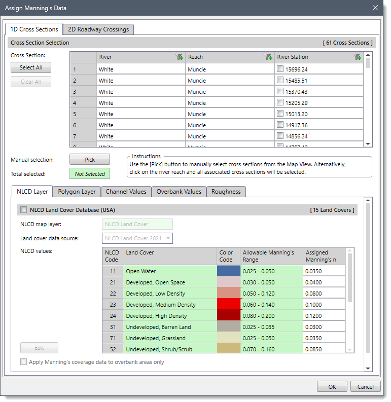
The above dialog box contains two panels:
The dialog box will default to either the 1D Cross Sections or 2D Roadway Crossings panel based on the following criteria:
The following sections describe how to use the Assign Manning’s Data command and interact with the above dialog box.
The 1D Cross Sections panel of the Assign Manning’s Data command is used to assign Manning’s roughness data to each selected cross section for the 1D modeling reaches.
The following sections are available in this panel:
This section is used to manually select the cross sections for purposes of assigning Manning’s roughness. If a cross section is already selected on the Map View prior to running this command, the same cross section will be shown selected within the table.
Alternatively, click the [Pick] button to interactively select the cross sections from the Map View. The user can also click on the river reach and all associated cross sections will be selected. Clicking the [Select All] button causes all the cross sections to be selected. The user can click the [Clear All] button to cancel the previous selection and redo the entire process. In addition, the user can filter the specific river reaches to be shown in the table listing. Once the cross sections are selected, the number of selected cross sections will be displayed in the Total selected read-only field.
The NLCD Layer displays both natural and man-made land cover using the national land cover developed by the Multi-Resolution Land Characteristics (MRLC) Consortium. The NLCD Layer tab panel contains the NLCD Land Cover Database (optional) checkbox option. This optional section allows the user to assign Manning’s roughness to the selected cross sections based on the land use information downloaded from the NLCD map service.
Note that for countries other than the USA, the software provides similar land cover databases. The content of this data panel will change to represent the one that is available for the project area. Currently, our software supports Africa, Australia, Canada, Europe, India, New Zealand, and the USA land cover database.
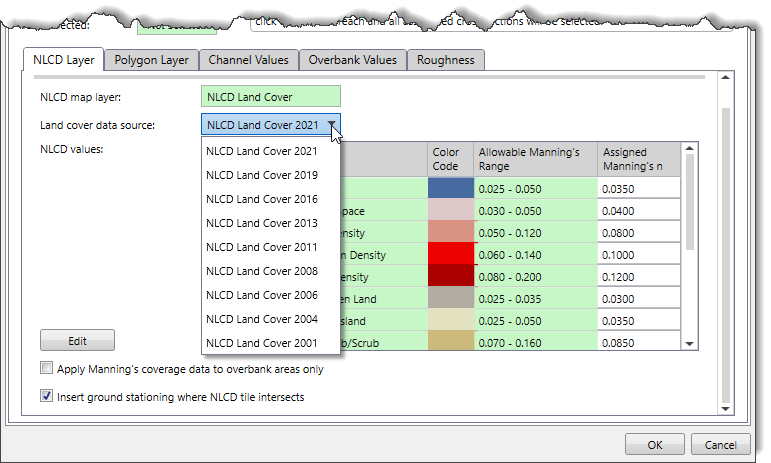
The Layer cover data source dropdown combo box allows the user to select which land use data sources to utilize for the newly created layer. By default, the software selects the most recent land use data. The following options are available in the dropdown combo box:
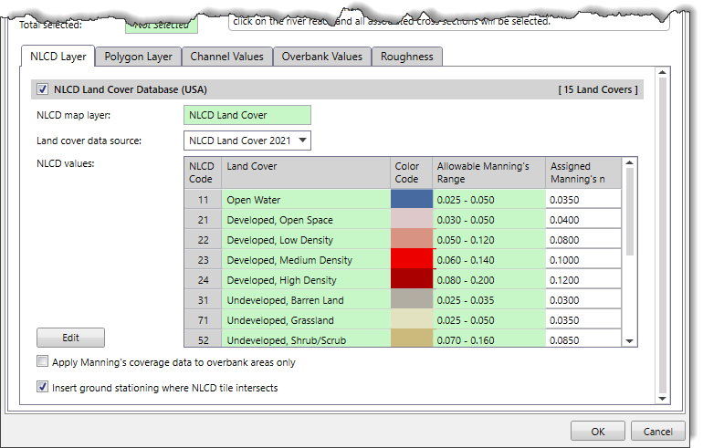
The Apply Manning’s coverage data to overbank areas only checkbox option causes the software to not assign channel roughness values (between the bank stations) from the Manning’s area layer. Generally, the channel roughness is uniform along a river or stream, and not defined by coverage area.
The Insert ground stationing where NLCD tile intersects checkbox option is checked by default. If this checkbox option is checked and if the NLCD tile is within 3 feet (1 meter) of an existing ground point, the existing ground point will be used. If not, a new ground point is inserted into the cross section at the point of intersection where the NLCD tile intersects. If this checkbox option is not checked, then the nearest cross section ground point to the point of intersection where the NLCD tile intersects will be used.
The user can click the [Edit] button to display the NLCD Land Cover dialog box that provides an editable data grid, allowing the user to change the Manning’s roughness values of different hydrologic soil groups.
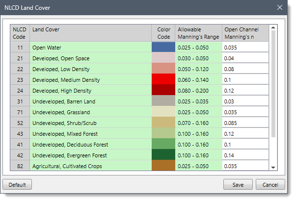
After editing the required cell values, the user can click the following buttons:
This optional section allows the user to map polygon shapefile data as Manning’s roughness data.
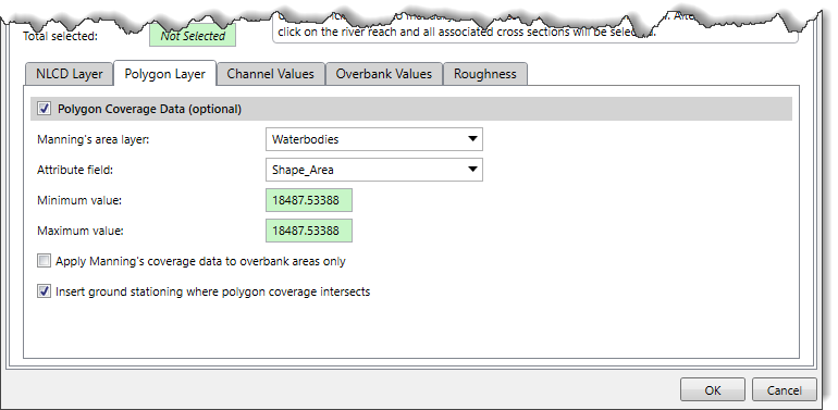
The Manning’s area layer dropdown combo box allows the user to select the layers that contain Manning’s roughness value. This dropdown combo box lists only loaded polygon shapefiles. If there is no layer selected, the user can still complete the assignment of Manning’s roughness using the default values.
The Attribute field dropdown combo box allows the user to select the corresponding Manning’s roughness attribute field contained within the selected roughness shapefile.
The Minimum value and Maximum value read-only fields show the minimum and maximum float values contained in the selected shapefile and attribute fields. This allows the user to determine if the selected attribute field is correct. If the selected attribute field does not contain float values, then these fields show Not Available.
Note that the Apply Manning’s coverage data to overbank areas only checkbox option works similarly to the Apply Manning’s coverage data to overbank areas only checkbox option provided in the NLCD Layer panel.
The Insert ground stationing where polygon coverage intersects checkbox option is checked by default. If this checkbox option is checked and if the Manning’s roughness polygon is within 3 feet (1 meter) of an existing ground point, the existing ground point will be used. If not, a new ground point is inserted (using linear interpolation) into the cross section at the point of intersection with the cross section and Manning’s roughness polygon. If this checkbox option is not checked, then the nearest cross section ground point to the point of intersection and Manning’s roughness polygon will be used.
This optional section allows the user to control Manning’s values for the channel. There are two options for assigning Manning’s roughness. The user can either choose the Set Manning’s to channel value or the Assign Manning’s value option.
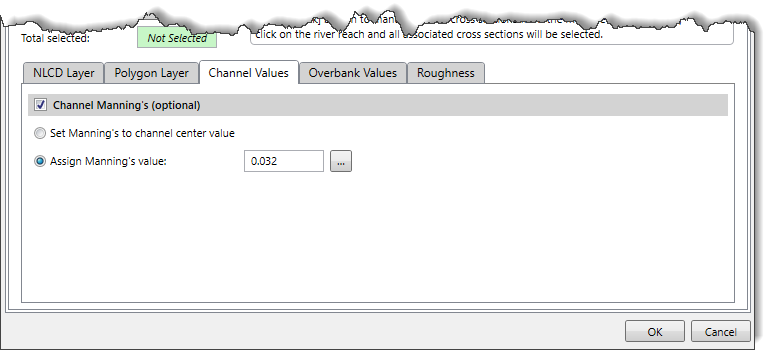
The Set Manning’s to channel center value option will set the Manning’s n value to a center value for all selected cross sections that have more than one n value inside of the channel.
The Assign Manning’s value option allows the user to change any individual Manning’s values for the selected cross section. By default, the software uses a value of 0.032. The user can also enter a different value or click the […] browse button to display the information table for Manning’s roughness values that can be assigned.
The Overbank Values tab panel is used to assign roughness values to the overbank parts of a cross section where the data contained in the NLCD Layer and Polygon Layer panels do not cover the cross section overbanks. These overbank values are only assigned if the Assign left overbank Manning’s value and Assign right overbank Manning’s value checkboxes are checked.
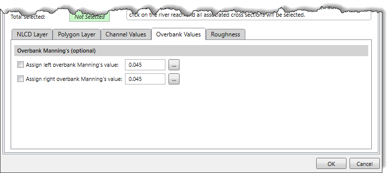
The Assign left overbank Manning’s value checkbox option allows the user to assign Manning’s roughness to the left overbank areas. By default, the software uses a value of 0.045. The user can also enter a different value or click the […] browse button to display the information table for Manning’s roughness values that can be assigned.
The Assign right overbank Manning’s value checkbox option allows the user to assign Manning’s roughness to the right overbank areas. By default, the software uses a value of 0.045. The user can also enter a different value or click the […] browse button to display the information table for Manning’s roughness values that can be assigned.
The Roughness tab panel is used to define the default values when a new cross section is created on the Map View using the assign or draw commands.
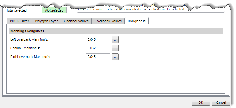
This panel provides the following fields to define default Manning’s roughness values:
The Left overbank Manning’s entry field allows the user to define the default Manning’s roughness to be applied to the left overbank areas (looking in a downstream direction) that do not have Manning’s roughness data defined. By default, the software uses a value of 0.045. The user can also enter a different value or click the […] browse button to display the information table for Manning’s roughness values that can be assigned. A blank entry is not allowed.
The Channel Manning’s entry field allows the user to define the default Manning’s roughness to be applied to the channel areas that do not have Manning’s roughness data defined. By default, the software uses a value of 0.032. The user can also enter a different value or click the […] browse button to display the information table for Manning’s roughness values that can be assigned. A blank entry is not allowed.
The Right overbank Manning’s entry field allows the user to define the default Manning’s roughness to be applied to the right overbank areas (looking in a downstream direction) that do not have Manning’s roughness data defined. By default, the software uses a value of 0.045. The user can also enter a different value or click the […] browse button to display the information table for Manning’s roughness values that can be assigned. A blank entry is not allowed.
When the data have been defined in the 1D Cross Sections panel of the Assign Manning’s Data dialog box, click the [OK] button. The software will then assign Manning’s roughness to each selected cross section for 1D modeling reaches.
The 2D Roadway Crossings panel of the Assign Manning’s Data command is used to assign Manning’s roughness data for the cross sections defined at a 2D roadway crossing.
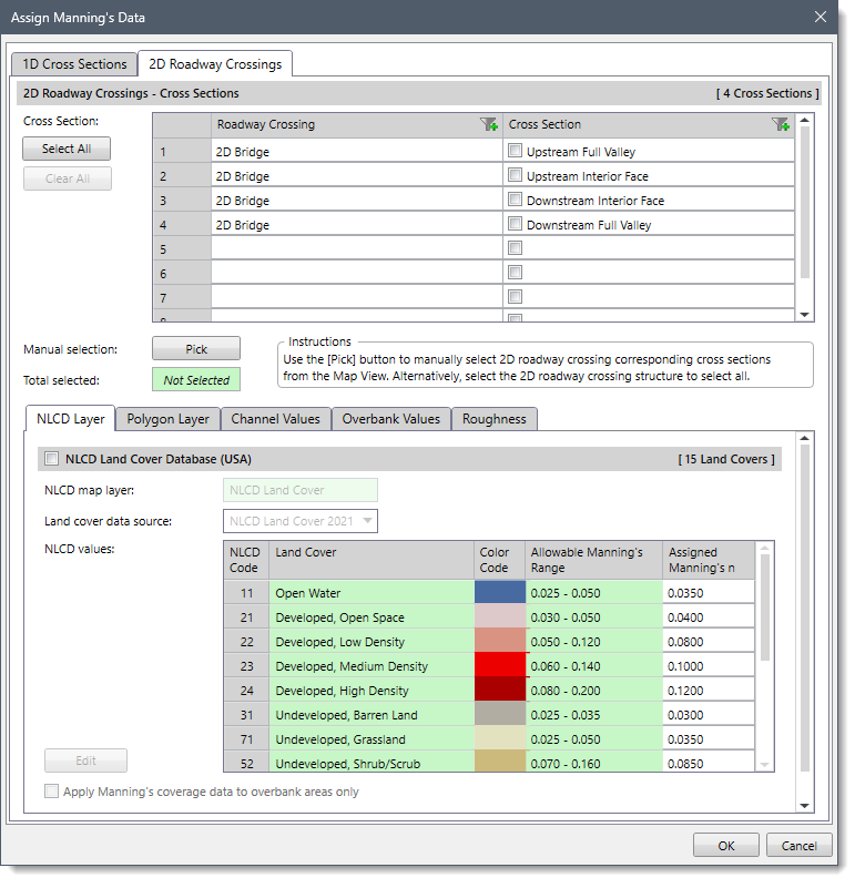
This section is used to manually select cross sections defined at a 2D roadway crossing for assigning Manning’s roughness. If a 2D roadway crossing corresponding cross section is already selected on the Map View prior to running this command, the same cross section will be shown selected within the table.
Alternatively, click the [Pick] button to interactively select the 2D roadway crossing corresponding cross sections from the Map View. The user can also click on the 2D roadway crossing structure and all associated cross sections will be selected. Clicking the [Select All] button causes all the cross sections to be selected. The user can click the [Clear All] button to cancel the previous selection and redo the entire process. Once the 2D roadway crossing corresponding cross sections are selected, the number of selected cross sections will be displayed in the Total selected read-only field.
Note that the remaining sections of this panel are similar to that of the 1D Cross Sections panel. Refer to the Assigning Manning’s Data for 1D Cross Sections part of this article to learn more about them.
When the data have been defined in the 2D Roadway Crossings panel, click the [OK] button. The software will then assign Manning’s roughness data to the selected cross sections defined at a 2D roadway crossing.


CivilGEO G2 Reviews
4.8/5.0 Rating, Over 230 Reviews

GeoHECRAS is recognized as the top Civil Engineering Design Software with an average of 4.8 out of 5.0 rating from over 230 real user reviews on G2.


We use cookies to give you the best online experience. By agreeing you accept the use of cookies in accordance with our cookie policy.
When you visit any web site, it may store or retrieve information on your browser, mostly in the form of cookies. Control your personal Cookie Services here.


