
Welcome to CivilGEO Knowledge Base
Welcome to CivilGEO Knowledge Base
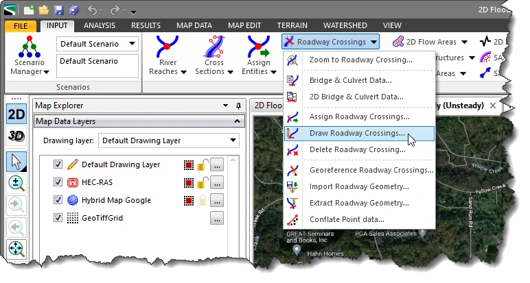
GeoHECRAS allows the user to model roadway crossings consisting of single or multiple bridge openings and culverts. Roadway crossings can also be drawn directly inside 2D flow areas to model 2D bridges.
Roadway crossings can be defined by either drawing or assigning the polyline using the following commands:
Existing roadway crossings can also be georeferenced to represent the roadway structure more accurately. Refer to this article in our knowledge base to learn how to georeference a roadway crossing.
The Draw Roadway Crossings command allows the user to interactively draw the centerline of the roadway crossing on the Map View.
Follow the steps below to use the Draw Roadway Crossings command:
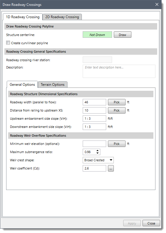
The above dialog box contains two panels:
The dialog box will default to either the 1D or 2D Roadway Crossing panel based on the following criteria:
The below sections describe how to draw a roadway crossing on the Map View and interact with the Draw Roadway Crossings dialog box.
The 1D Roadway Crossing panel of the Draw Roadway Crossings command is used to draw 1D roadway crossings.
The following sections are available in this panel:
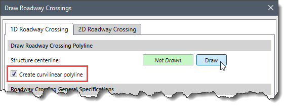
This section is used to draw the 1D roadway crossings on the Map View using polylines.
To draw a roadway crossing polyline, follow the steps below:
 Note that if the user clicks the [Draw] button and tries to draw the bridge centerline on a 2D mesh, then the software will automatically switch to the 2D Roadway Crossing panel.
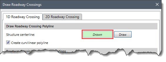
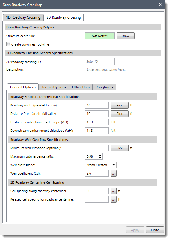
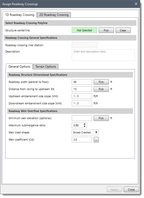
This section is used to provide general specifications for the roadway crossing.
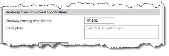
Note that the software automatically picks up the value for the Roadway crossing river station. This river station ID identifies the upstream end of the roadway crossing. The user can use the Description box to describe the location of the roadway crossing in more detail.
The General Options tabbed panel is used to specify the structural dimensions and weir overflow specifications of the roadway crossing.
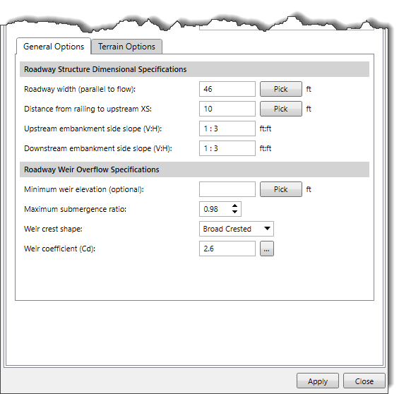
This section is used to define the width, distance, and slope of the road crossing.
The Roadway width (parallel to flow) entry field is used to enter the width of the roadway crossing along the stream. Alternatively, the user can click the [Pick] button to measure roadway width parallel to flow from the Map View.
The Distance from railing to upstream XS entry field is used to enter the distance between the upstream side of the roadway and the cross section immediately upstream of the roadway. Alternatively, the user can click the [Pick] button to measure the distance from the Map View.
The Upstream embankment side slope (V:H) entry field is used to enter the slope of the road embankment on the upstream side of the roadway. The slope should be entered as the horizontal to vertical distance ratio of the roadway crossing.
The Downstream embankment side slope (V:H) entry field is used to enter the slope of the road embankment on the downstream side of the roadway. The slope should be entered as the horizontal to vertical distance ratio of the roadway crossing.
This section is used to define the minimum weir elevation, maximum submergence ratio, weir crest shape, and weir coefficient for an overflow weir on a roadway.
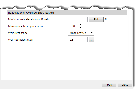
The Minimum weir elevation (optional) entry field allows the user to enter the minimum elevation for which weir flow will begin to be evaluated. If this field is left blank, the elevation that triggers weir flow is based on the lowest high chord elevation on the upstream side of the roadway. Alternatively, the user can click the [Pick] button to select elevation from the cross section on the Map View.
The Maximum submergence ratio entry field defines the maximum allowable submergence ratio that can occur during weir flow calculations over the roadway. By default, the software uses a value of 0.98 (98 percent submerged).
The Overflow weir crest shape dropdown combo box entry allows the user to specify weir types. There are two options available: Broad Crested and Ogee. The user can choose the weir type that best matches the problem.
If the user selects the Ogee shaped weir, two additional parameters: Spillway approach height and Design energy head are displayed in the Roadway Weir Overflow Specifications section.
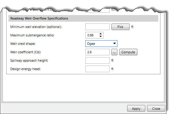
The Spillway approach height entry field defines the height which is equal to the elevation of the spillway crest minus the mean elevation of the ground just upstream of the spillway.
The Design energy head entry field defines the height which is equal to the energy grade line elevation minus the elevation of the spillway crest.
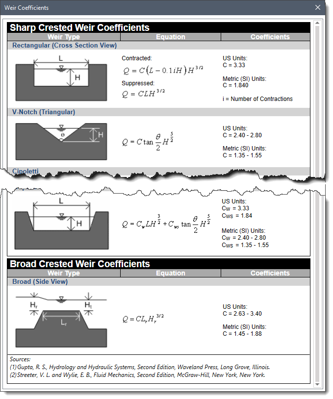
The Weir Coefficient (Cd) entry field allows the user to enter a weir coefficient that will be used in the weir computations. Note that different coefficients may be selected, depending on use of Metric (SI) or US Units. By default, the software uses a value of 2.6. Clicking on the […] button will display a lookup dialog box containing weir coefficients.
Note that if the Ogee shaped weir is selected, the user can click [Compute] and compute the weir coefficient based on the approach and design energy head.
The Terrain Options tabbed panel is used to define the source elevation data that can be used to extract the roadway geometry defined from the digital terrain layers.
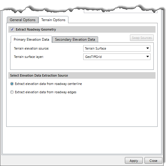
This optional section is used to select the source elevation data necessary to extract roadway geometry. By default, the Extract Roadway Geometry section is enabled. The user can uncheck the Extract Roadway Geometry checkbox to disable this section. If this section is disabled, the sections that appear below it will be unavailable (i.e., grayed out), and the software will not extract the roadway geometry.
The user can use the Primary and Secondary Elevation Data panels to define the primary and secondary (if available in the project) elevation data sources for extracting roadway geometry. Depending upon the elevation data source type that is selected, different options are provided to specify additional elevation data information.
Refer to this article in our knowledge base for information on the types of terrain elevation data that can be used to construct cross sections.
When a secondary elevation data source is available, the software will form a concave hull around the primary elevation data source to identify its bounds. For locations where elevation data from the primary data source are unavailable, the software will use elevation data from the secondary data source.
Note that the user cannot utilize the same data source to define both primary and secondary elevation data.
The user can click the [Swap Sources] button to swap the selected elevation source from primary elevation data to secondary elevation data and vice versa.
This section is used to define the location of the extracted terrain source on the Map View.
The Extract elevation data from roadway centerline option is used to extract the roadway geometry from the centerline of the roadway. By default, this option is selected.
The Extract elevation data from roadway edges option is used to extract the roadway geometry from the edges (left and right) of the roadway.
When the data has been defined in the 1D Roadway Crossing panel, click the [Apply] button. The software will create a roadway crossing using the roadway centerline drawn by the user.
The 2D Roadway Crossing panel of the Draw Roadway Crossings command is used to draw 2D roadway crossings.
Note that most of the sections of this panel are similar to that of the 1D Roadway Crossing panel.
Similar to drawing a 1D roadway crossing, the user can draw the 2D roadway crossing centerline using the Draw 2D Roadway Crossing Polyline section and define the general specifications for creating the roadway crossing.
Note that if the user clicks the [Draw] button of the 2D Roadway Crossing panel and tries to draw the bridge centerline on a river reach, then the software will automatically switch to the 1D Roadway Crossing panel wherein the user can fill in the required information.
Additionally, for 2D roadway crossings, the user must specify the cell spacing values along the roadway centerline in the 2D Roadway Centerline Cell Spacing section.
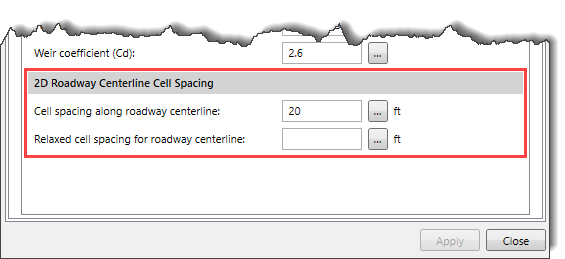
The following entries are provided in this section:
When the data has been defined in the 2D Roadway Crossing panel, click the [Apply] button. The software will create a roadway crossing using the roadway centerline drawn by the user.
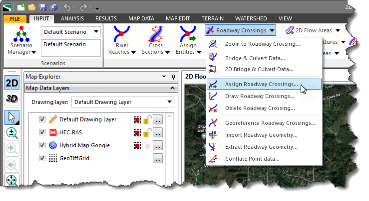
The Assign Roadway Crossings command allows the user to manually assign an already existing roadway crossing centerline as a roadway crossing.
Follow the steps below to use the Assign Roadway Crossings command:
Note that this dialog box is similar to the Draw Roadway Crossings dialog box. It follows similar criteria and defaults to either the 1D or 2D Roadway Crossing panel.
The below sections describe how to assign a roadway crossing on the Map View and interact with the above dialog box.
The 1D Roadway Crossing panel of the Assign Roadway Crossings dialog box is used to assign an existing polyline as the roadway centerline for 1D roadway crossings.

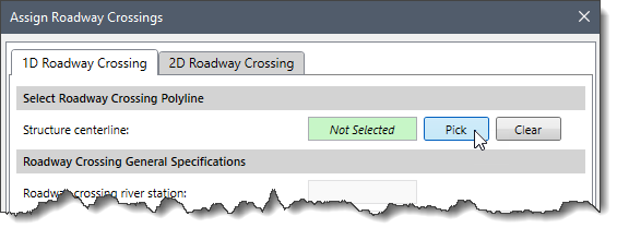
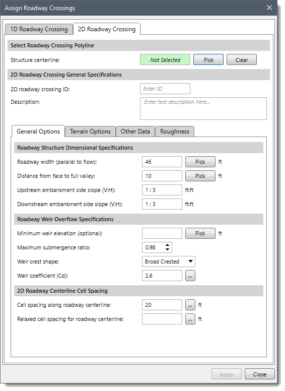
The Select Roadway Crossing Polyline section allows the user to select the existing polyline representing the roadway centerline from the Map View.
Follow the steps below to select the roadway centerline from the Map View:
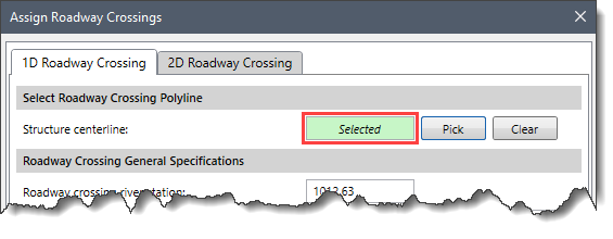
When the polyline is selected, the user can define the general specifications for creating the roadway crossing.
Note that the remaining sections of the 1D Roadway Crossing panel are similar to that of the Draw Roadway Crossings command. To learn more about them, see the above sections of this article.
When the data have been defined in the 1D Roadway Crossings panel, click the [Apply] button. The software will then assign the selected polyline as a roadway crossing.
The 2D Roadway Crossing panel of the Assign Roadway Crossings dialog box is used to assign an existing polyline as the roadway centerline for 2D roadway crossings.
Note that most of the sections of this panel are similar to that of the 1D Roadway Crossing panel.
Similar to selecting a 1D roadway crossing polyline, the user can select the 2D roadway crossing polyline using the Select 2D Roadway Crossing Polyline section and define the general specifications for creating the 2D roadway crossing.
Additionally, for 2D roadway crossings, the user must specify the cell spacing values along the roadway centerline in the 2D Roadway Centerline Cell Spacing section.
When the data has been defined in the 2D Roadway Crossings panel, click the [Apply] button. The software will then assign the selected polyline as a 2D roadway crossing.


CivilGEO G2 Reviews
4.8/5.0 Rating, Over 230 Reviews

GeoHECRAS is recognized as the top Civil Engineering Design Software with an average of 4.8 out of 5.0 rating from over 230 real user reviews on G2.


We use cookies to give you the best online experience. By agreeing you accept the use of cookies in accordance with our cookie policy.
When you visit any web site, it may store or retrieve information on your browser, mostly in the form of cookies. Control your personal Cookie Services here.


