Breaklines are used to define sudden breaks in the terrain surface and interruptions in surface water flow. Breaklines should be added where there are:
- Sudden changes in bathymetry, like top of bank or toe of slope
- Barrier to flow, such as a levee or roadway embankment
- Definitive flow direction, such as a stream or river centerline
- Cell size refinement, such as where mutiple changes occur in a small area
Breaklines force the 2D mesh cell faces to align with the breakline and prevent cells from crossing the breakline. Breaklines are critical to create an accurate 2D mesh so that the mesh properly represents an accurate bathymetric model.
In GeoHECRAS 2D, flow area breaklines can be defined by either drawing or assigning breaklines on the Map View using the following commands:
- Draw 2D Flow Area Breaklines
- Assign 2D Flow Area Breaklines
Drawing/Assigning 2D Flow Area Breaklines
The Draw/Assign 2D Flow Area Breaklines command is used to manually draw/assign multiple breaklines on the Map View, one after another, until completed.
Follow the steps below to use the Draw/Assign 2D Flow Area Breaklines command:
- From the Input ribbon menu, expand the 2D Breaklines dropdown menu and then choose the Draw/Assign 2D Flow Area Breaklines command.
![[12:50 PM] Abhishek Mishra 1. Draw/Assign 2D Flow Area Breaklines Input ribbon menu command 2. Draw 2D Flow Area Breaklines dialog box 3. Assign 2D Flow Area Breaklines dialog box 4. [Draw] button 5. Breakline polyline read-only field 6. [Pick] button 7. Breakline polylines/polygons read-only field 8. Breakline Parameters (Optional) section Draw and Assign 2D Flow Area Breaklines Images.zip](/wp-content/uploads/sites/25/2023/05/Draw-and-Assign-2D-Flow-Area-Breaklines-Image-1.png)
- The following dialog boxes will be displayed.
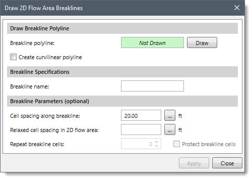
- Draw 2D Flow Area Breaklines:
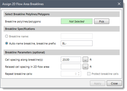
- Assign 2D Flow Area Breaklines:
The following sections describe how to use the Draw and Assign 2D Flow Area Breaklines commands and interact with the above dialog boxes.
Drawing 2D Flow Area Breaklines
Drawing Breakline Polyline
The Draw Breakline Polyline section is used to draw 2D flow area breaklines on the Map View using polylines. To draw a breakline polyline, follow the steps below:
- Click the [Draw] button.
![[Draw] button](/wp-content/uploads/sites/25/2023/05/Draw-and-Assign-2D-Flow-Area-Breaklines-Image-4.png)
- The Draw 2D Flow Area Breaklines dialog box will temporarily disappear, and a prompt will be displayed on the status bar informing the user on what to do next.
- Draw the breakline polylines on the map View.
Note: To draw the polyline using curvilinear segments, use Create curvilinear polyline checkbox option.
- After the breakline polyline has been drawn, press the [Enter] key or right-click and select Done from the displayed context menu.
- The Draw 2D Flow Area Breaklines dialog box will be redisplayed, and the status of the Breakline polyline read-only field will be changed from Not Drawn to Drawn.
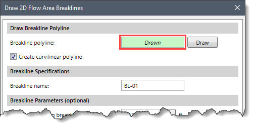
- In the Breakline Specifications section, the software automatically names the drawn breakline. Note that the user can also change the name to whatever is desired from the Breakline name entry field.
Assigning 2D Flow Area Breaklines
Selecting Breakline Polylines/Polygons
The Select Breakline Polylines/Polygons section is used to assign breaklines from previously defined CAD or GIS polylines/polygons on the Map View. To assign breakline polylines/polygons, follow the steps below:
- Click the [Pick] button.
![[Pick] button](/wp-content/uploads/sites/25/2023/05/Draw-and-Assign-2D-Flow-Area-Breaklines-Image-6.png)
- The Assign 2D Flow Area Breaklines dialog box will temporarily disappear, and a prompt will be displayed on the status bar instructing the user to select the CAD or GIS polylines/polygons.
- Click on the CAD or GIS polylines/polygons on the Map View to select them.
- After the breakline polylines/polygons have been selected, press the [Enter] key or right-click and select Done from the displayed context menu.
- The Assign 2D Flow Area Breaklines dialog box will be redisplayed and the number of selected polylines/polygons will be displayed in the Breakline polylines/polygons read-only field.
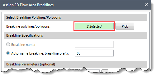
- In the Breakline Specifications section, define the prefix for the names of the breaklines in the Auto-name breakline, breakline prefix entry field.
Note that the Breakline name option is only available when a single polyline/polygon is selected. The user can then define the name of the breakline in the Breakline name entry field. Otherwise, the software auto-names the breaklines using the defined prefix, for example, BL-##, where ## represents the breaklines count (i.e., 01, 02, and so on) and BL represents the prefix.
Breakline Parameters (Optional)
This section is common to both the Draw 2D Flow Area Breaklines and Assign 2D Flow Area Breaklines dialog boxes and allows the user to define additional parameters to control how 2D cells are created in the vicinity of the breakline.
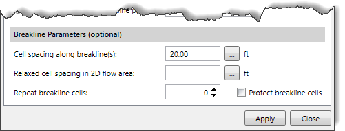
The following options are provided in this section:
- Cell spacing along breakline(s)
This entry represents cell spacing along the breakline. If this entry is left blank, then the cell spacing used in the vicinity of the breakline will be used. Click on the […] button to measure the breakline cell spacing from the Map View.
- Relaxed cell spacing in 2D flow area
This entry represents the cell spacing further away from the breakline. If this entry is left blank, then the cell spacing used in the vicinity of the breakline will be used. This value should not be the same as the Cell spacing along breakline(s) value or cell errors may be introduced along the breakline. Click on the […] button to measure the breakline cell spacing from the Map View.
- Repeat breakline cells
This spin control causes additional layers of identically sized cells to be created adjacent to the breakline cells.
- Protect breakline cells
This checkbox causes the software to leave any manual edits of the cells that align with the breakline as they are.
When all the data have been defined, click the [Apply] button to complete the process of drawing or assigning breaklines.


