
Welcome to CivilGEO Knowledge Base
Welcome to CivilGEO Knowledge Base
In CivilGEO’s software, the following basic element types are used to create engineering entities:
The user can select multiple project elements while pressing and holding down the [Ctrl] key during the element selection. To rotate the selected elements, right-click and choose Graphic Edit from the displayed context menu. Alternatively, press the [F2] key to directly enable the Graphic Edit option for the selected element.
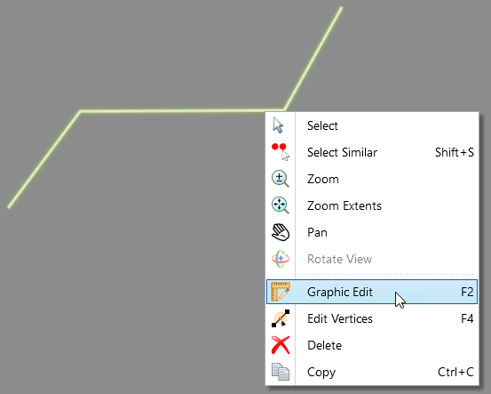
Note that graphical editing can be performed only on the polyline and polygon project elements.
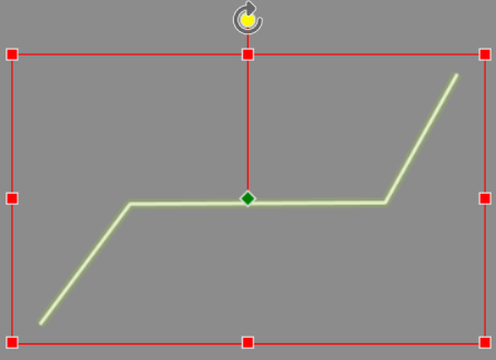
Once the graphical editing option is enabled, hovering/clicking on the rotation grip (i.e., a yellow color node) will cause the rotation center/pivot point (i.e., a green color node) to be then shown at the center of the selection bounding box. In addition, the selected rotation grip will be highlighted, and the cursor will change to a rotation cursor.
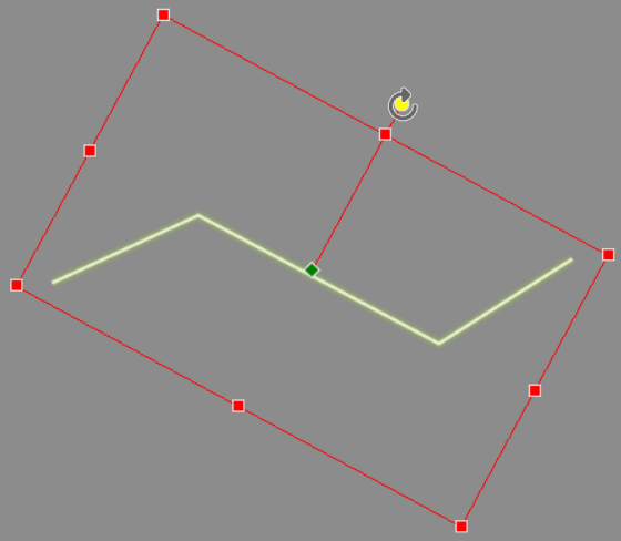
The user can then drag the rotation grip and the selected elements will then rotate around the rotation center reference point.
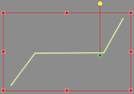
To reposition the rotation center reference point, click and drag it to a new location.
To resize the selected elements, click on one of the corners or side grips of the selection bounding box and drag. The selected elements will then be resized. Clicking on a grip causes it to become selected and highlighted. Releasing the mouse cursor from the side grip causes the grip to become non-selected and non-highlighted.
When resizing the selected elements using the corner grips, the selected elements are resized proportionally with the opposite corner grip acting as an anchor point.
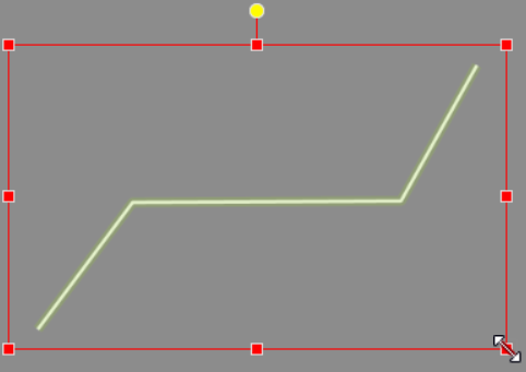
To resize the selected elements non-proportionally using the corner grips, hold down the [Shift] key while dragging the corner grip.
When resizing the selected elements using the side grips, the selected elements are resized non-proportionally with the opposite edge side grip acting as an anchor point.
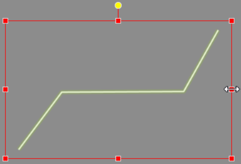
To resize the selected elements proportionally using the side grips, hold down the [Shift] key while dragging the side grip.
Note that clicking the mouse cursor at a random Map View location or pressing the [ESC] key disables the Graphic Edit mode for the selected elements.


CivilGEO G2 Reviews
4.8/5.0 Rating, Over 230 Reviews

GeoHECRAS is recognized as the top Civil Engineering Design Software with an average of 4.8 out of 5.0 rating from over 230 real user reviews on G2.


We use cookies to give you the best online experience. By agreeing you accept the use of cookies in accordance with our cookie policy.
When you visit any web site, it may store or retrieve information on your browser, mostly in the form of cookies. Control your personal Cookie Services here.


