In EPA SWMM, a cyclic loop network refers to a connected series of channels or pipes within the drainage system where the flow can travel in a continuous loop, i.e., starting and ending at the same point. Since the flow does not typically circulate in a continuous loop without a driving force, such as a pump, it can cause computational instability in the model, further leading to conflicts in flow calculations.
A cyclic network loop error typically arises in a complex drainage system or network having interconnected nodes and conduits. Theoretically, in such a network, water could flow endlessly in a circular pattern without reaching an outlet. Consequently, determining the flow direction and solving the equations governing the flow becomes difficult for the software, impacting the accuracy of the SWMM simulation.
Factors Causing the Formation of Cyclic Loop Network
A cyclic loop network in a complex drainage system can form due to several factors, such as:
- Incorrect Node Connections
If interconnected nodes, such as routing junctions or terminal outfalls, are not connected as designed, paths that link back to an earlier point in the network may result, forming a loop.
- Design Errors
Misplacing or duplicating pipes and routing junctions in the model design can result in unintended loops.
- Improper Flow Direction
If pipes are oriented incorrectly and lead back to a previous node, a cyclic loop can be created. Hence, accurate flow direction must be maintained throughout the drainage system.
- Lack of Outlets
In a drainage network without proper outfalls or discharge points, water may circulate through the system indefinitely, resulting in a cyclic loop network.
Steps to Fix Cyclic Loop Network Errors in EPA SWMM
The following steps can be taken to fix a cyclic loop network error in EPA SWMM:
- Identifying Loop
Review the error message or computed results generated by the software to identify the part of the drainage network demonstrating cyclic loops.
- Checking Node Connections
Ensure that the interconnected nodes are correctly connected to pipes or channels, contributing to the flow in a clear direction towards a downstream node.
- Eliminating Unnecessary Connections
Simplify the drainage network by removing redundant or unnecessary connections that form cyclic loops.
- Converting to Series Flow
Convert branch connections into series flow paths rather than parallel paths if they are displaying a cyclic loop error.
- Using Outlet Nodes
Use overflow conditions or outlet nodes to guide the flow in one direction and prevent cyclic scenarios.
- Rerunning the Model
After making the necessary adjustments, run the model again to check if the cyclic loop error has been resolved.
How to Fix a Cyclic Loop Network Error
In GeoSTORM, cyclic loop network errors can be resolved by selecting a suitable flow routing method. The following flow routing methods are supported by the software:
- Hydrodynamic
- Steady State Peak Flow
- Kinematic Wave
Refer to this article in our knowledge base to learn more about the flow routing methods supported by GeoSTORM.
Steady State Peak Flow and Kinematic Wave routing methods only support dendritic (or tree-like) routing networks. Consequently, the software displays an error when performing stormwater analysis in a cyclic loop network.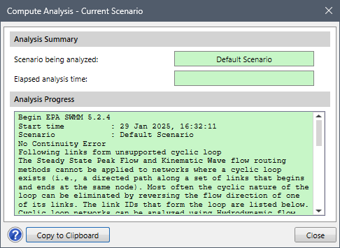
In such situations, the Hydrodynamic routing method must be specified. This routing method offers a more comprehensive and accurate simulation of flow conditions in a complex drainage network.
Follow the steps below to select the Hydrodynamic routing method in GeoSTORM:
- From the Input ribbon menu, select the Scenario Manager command.

- The Scenario Manager dialog box will be displayed.

- From the Flow routing method dropdown combo box, select the Hydrodynamic routing method.

- Now, from the Analysis ribbon menu, select the Compute Analysis command to perform stormwater analysis.
- The software will successfully run the analysis.

Note that the Flow routing method dropdown combo box will be displayed as disabled when the Rational Method is selected as the hydrology analysis engine.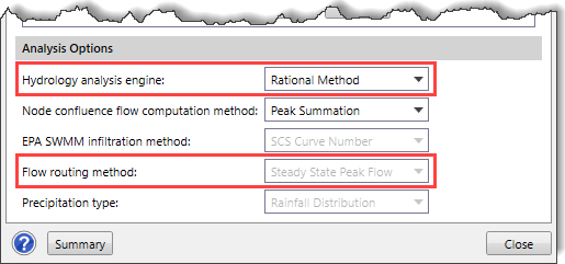
Therefore, in the case of the Rational Method, the user needs to simplify the network by removing or modifying the node connections forming a cyclic loop. Alternatively, the user can eliminate the cyclic loop network by reversing the direction of one of its links (i.e., switching the inlet and outlet nodes of the link).