Urban subbasins with storm sewer interconnects are drainage areas that are hydraulically linked through an underground network of inlets, manholes, pipes, and outfalls. These components form a hierarchical storm sewer system that collects runoff, conveys it through storm sewer pipes, and discharges it at designated outfall locations. This connectivity is essential for reducing flooding and ensuring effective stormwater management.
When designing storm sewer systems, factors such as subbasin imperviousness, topography, and drainage characteristics must be considered. These factors directly influence the runoff coefficient and flow calculations, which are critical for accurately modeling storm sewer systems in urban environments.
In GeoSTORM, users can model interconnected storm sewer networks by assigning subbasins to manholes or junctions, creating hydraulic connectivity, and analyzing runoff with hydrological tools and profile plots. This interconnected modeling approach is essential for understanding the collective impact of storm events on urban infrastructure and flood risk.
Why Model Subbasins with Storm Sewer Interconnects
Inaccurately designed storm sewer systems can lead to flooding, erosion, and infrastructure damage, resulting in costly economic and environmental consequences. A well-designed storm sewer system provides several key benefits, such as:
- Sustainable urban development that ensures reliable and efficient stormwater infrastructure.
- Reduced flood risk by conveying runoff efficiently and minimizing surface water accumulation.
- Safeguarded infrastructure and property by reducing the risk of damage to roads, utilities, and buildings.
- Protection of public health and safety by reducing exposure to waterborne hazards and preventing localized flooding.
Key Considerations for Effective Hydrological Management
The following factors are essential for effective hydrological management in the design of storm sewer systems:
- Assess catchment characteristics, including rainfall patterns, soil types, and land use.
- Conduct hydrological analysis and modeling to estimate stormwater runoff rates and volumes.
- Design the system for anticipated flows, accounting for peak discharges and total runoff volumes.
Design Principles and Best Practices
Hydrological Analysis
Hydrological analysis is the foundation of storm sewer system design. It estimates the volume and peak rate of runoff generated from each subbasin during storm events.
Common hydrological analysis methods include:
- Rational Method – Ideal for small urban catchments; estimates peak discharge using rainfall intensity, runoff coefficient, and time of concentration.
- SCS Curve Number Method – Considers soil type, land use, and antecedent moisture conditions to estimate runoff.
Pipe Sizing
Proper pipe sizing is essential to ensure that storm sewer systems can convey peak flows without surcharge or overflow.
Key considerations for pipe sizing include:
- Expected peak flow from upstream subbasins.
- Pipe characteristics, such as material, roughness, and slope.
- Existing infrastructure and site constraints may limit pipe alignment or diameter.
Pipe Slope
The slope of storm sewer pipes is a critical factor for maintaining efficient flow and preventing water from standing or accumulating within the system. The required slope depends on the pipe size, material, and anticipated flow rate. Typically, the slope should be sufficient to maintain a minimum flow velocity of 0.75 m/s (2.5 ft/s) during peak conditions.
Components of Storm Sewer Systems
A well-designed storm sewer system consists of several interconnected components, each playing a vital role in transporting runoff from multiple subbasins. Understanding these elements is essential for effectively modeling and managing urban drainage systems.
Subbasins
Subbasins represent individual drainage areas that produce surface runoff during storm events. Subbasins are delineated based on topography, land use, and flow direction. In GeoSTORM, subbasins can be assigned directly to manholes or junctions within the storm sewer network. Refer to this article in our knowledge base to learn how to draw subbasins.
Inlets and Catch Basins
Inlets act as collection points where stormwater enters the underground sewer system. Inlets are positioned at low points in roads, parking lots, or other paved areas to capture runoff from impervious surfaces.
Catch basins are underground chambers positioned beneath inlets. Catch basins temporarily store stormwater runoff and trap sediment and debris to prevent clogging in downstream pipes. Regular maintenance of catch basins is essential to ensure effective pollutant removal and uninterrupted flow.
Pipes
Pipes convey stormwater from inlets and catch basins to downstream components such as manholes and outfalls. Pipes are typically made of materials such as concrete, cast iron, and PVC. Refer to this article in our knowledge base to learn how to draw pipes.
Manholes
Manholes are covered openings in the ground that provide access to storm sewer pipes for inspection, maintenance, and cleaning. Manholes are typically located at junctions, changes in pipe direction, or at regular intervals along the pipe. Manholes are usually covered with heavy lids to prevent unauthorized access and ensure safety. Refer to this article in our knowledge base to learn how to draw manholes.
Terminal Outfalls
Terminal outfalls are the discharge points where stormwater is released into a larger body of water, such as a river, lake, or ocean. Refer to this article in our knowledge base to learn how to draw terminal outfalls.
How Subbasins Connect to Storm Sewer Systems
Subbasins can be connected to the storm sewer system in the following ways:
Subbasin-to-Manhole/Junction Connection
- Delineate subbasins based on topography, land use, and flow direction.
- Assign each subbasin an outlet point, typically a nearby manhole or junction.
- Direct runoff from the subbasin through this outlet into the underground pipe network.
Routing through the Storm Sewer Network
- Route runoff through pipes, manholes, and catch basins until it reaches a terminal outfall.
- Use additional components such as storage units, control structures, or overflow connections to regulate flow or handle surcharges.
Observing Pipe Profiles
After defining subbasin connections and routing flows through the storm sewer system, it is important to review pipe profiles to visualize and validate overall storm sewer system performance.
In GeoSTORM, the Profile Plot command allows the user to display stormwater pipe and ditch profile (long section) plots. A profile plot helps you:
- Visualize the underground layout of pipes, manholes, and outfalls.
- Display the Hydraulic Grade Line (HGL) and Energy Grade Line (EGL) to check hydraulic performance.
- Adjust pipe diameters, slopes, and inverts directly within the profile view.
- Export profiles to AutoCAD and MicroStation, and other formats for design documentation.
Refer to this article in our knowledge base to learn more about the Profile Plot command.
The following image shows how subbasins are connected through a storm sewer network in GeoSTORM.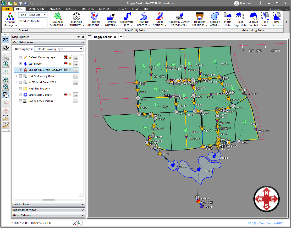
Advantages of Storm Sewer Systems
The key benefits of modeling storm sewer systems include:
- Public Safety
Prevents water accumulation on streets and sidewalks during storm events, reducing traffic hazards and risks of injury.
- Property Protection
Minimizes the risk of water intrusion, erosion, and flood damage to buildings, roads, and underground utilities.
- Environmental Compliance
Controls discharge and captures sediment to reduce pollutant transport to natural water bodies, supporting regulatory compliance and environmental health.
- Infrastructure Planning
Provides insights into system capacity and performance, helping engineers plan upgrades, optimize pipe sizing, and reduce costly future retrofits.