Storage areas can be defined by drawing the boundary of the area using the Draw Storage Areas command, or by assigning an already drawn polyline or polygon as the boundary using the Assign Storage Areas command. Refer to this article in our knowledge base on how to create a storage area.
Once a storage area has been defined, the user can enter data to describe the storage area. In GeoHECRAS, the Storage Area Data command can be used to view or modify the storage area data. This data includes the area of storage, the minimum elevation, and the elevation-versus-volume relationship. The elevation-versus-volume relationship is a curve that shows how the volume of the storage area changes as the elevation of the water surface changes.
Storage areas can be connected to other storage areas, cross sections, or lateral structures. When a storage area is connected to another storage area, the flow between the two areas is calculated using the storage area’s elevation-versus-volume relationship. When a storage area is connected to a cross section or lateral structure, the flow between the storage area and the cross section or lateral structure is calculated using the cross section’s or lateral structure’s hydraulic parameters.
Storage areas can be used to model a variety of hydrologic processes, including flood routing, water quality, and sediment transport. By using storage areas, GeoHECRAS can be used to simulate the effects of these processes on a river system.
This article describes how to use the Storage Area Data command in GeoHECRAS software.
Follow the steps below to view or modify the storage area data:
- From the Input ribbon menu, click the Storage Areas dropdown menu and then select the Storage Area Data command. Alternatively, the user can double-click on the storage area from the Map View.

- The Storage Area Data dialog box will be displayed.

The following sections describe how to use the Storage Area Data command and interact with the above dialog box.
Selecting Storage Area
The Select Storage Area section allows the user to select the storage area in order to define the storage area data. The user can create a new storage area, copy existing storage area data to a new storage area, and delete a storage area. In addition, the user can navigate between storage areas and enter a description detailing the current storage area.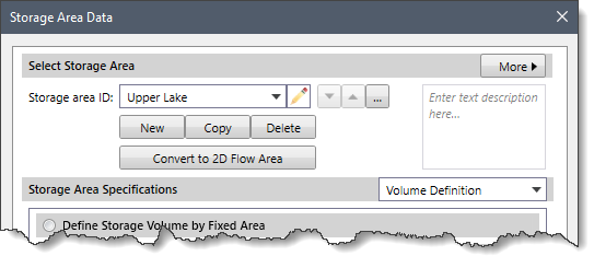
The following entries are provided in this section:
- Storage area ID
This editable dropdown combo box displays the storage area(s) defined in the current scenario of the project. Click on the edit option (i.e., pencil icon) to edit the storage area ID. The user can navigate between the available storage areas using the Up and Down arrow buttons. Alternatively, the user can click the […] button to select the storage area from the Map View. Note that the Up and Down arrow buttons will be disabled (i.e., grayed out) if the current scenario of the project contains only one storage area. - Description
This optional entry field allows the user to add additional information to describe the current storage area. - New
The [New] button allows the user to draw a new storage area on the Map View. Note that the newly created storage area name must be unique. Otherwise, a warning dialog box is displayed, and the user is then returned to the Storage area ID field to change the ID. - Copy
The [Copy] button allows the user to create a copy of the current storage area on the Map View. When this command is executed, the software automatically provides a unique default name for the duplicated storage area. The cursor is then placed into the Storage area ID. The user can go with the default name or enter a different valid and unique ID before moving on to add any other data. - Delete
The [Delete] button allows the user to delete the current storage area and its associated data from the current scenario of the project. - Less/More
The [< Less] and [More >] buttons at the Select Storage Area section header allow the user to expand or collapse the Storage Area Volume Plot section. - Convert to 2D Flow Area
The [Convert to 2D Flow Area] button allows the user to convert the current storage area to a 2D flow area. Clicking on the [Convert to 2D Flow Area] button will display the following confirmational dialog box.![[Convert to 2D Flow Area] button - Confirm dialog box](/wp-content/uploads/sites/25/2023/12/HEC-RAS-Storage-Area-Data-Command-Image-4.png)
Click the [Yes] button and the selected storage area will be converted to a 2D flow area. To abort the process, click the [No] button.
Storage Area Specifications
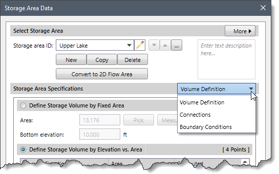
The Storage Area Specifications dropdown combo box contains several data panel entries that allow the user to define storage area data. The following data panel entries are listed in the dropdown combo box:
- Volume Definition
- Connections
- Boundary Conditions
Volume Definition
This panel provides different ways of defining the storage area volume. By default, the Volume Definition panel is selected when the Storage Area Data dialog box is displayed.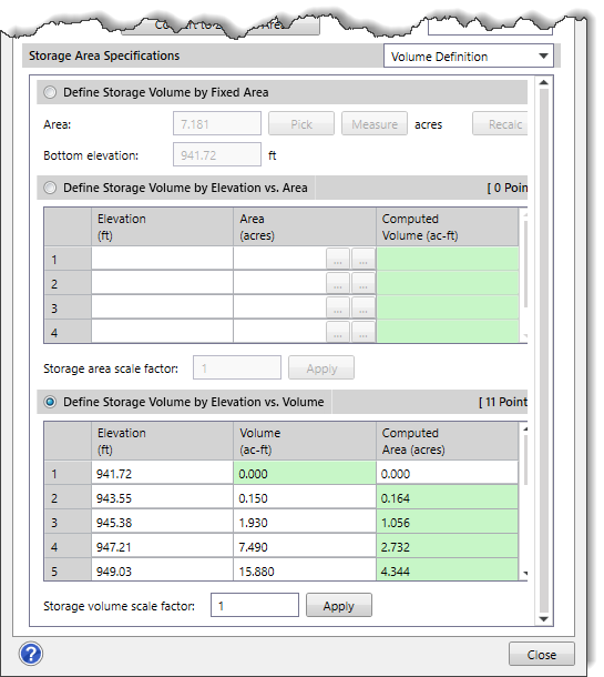
The following sections describe the Volume Definition data panel:
Defining Storage Volume by Fixed Area
The Define Storage Volume by Fixed Area radio button section allows the volume of the storage area to be defined with a fixed area and a bottom (minimum) elevation. By default, this radio button section is selected.
Note: The storage area is assumed to have the same area at all elevations, therefore the volume is simply the depth times the area.
The following options are provided:
- Area
This entry field is used to define a fixed area for the storage area. Alternatively, click the [Pick] button to select the polyline/polygon from the Map View to define an area for the storage area. Clicking on the [Measure] button allows the user to manually measure the area from the Map View. Clicking on the [Recalc] button allows the user to recalculate the area of the digitized storage area. - Bottom elevation
This entry field is used to manually define the bottom (minimum) elevation of the storage area.
Defining Storage Volume by Elevation vs. Area
The Define Storage Volume by Elevation vs. Area radio button section allows the volume of the storage area to be defined by a table of elevations and corresponding areas. The Storage area scale factor entry allows the user to adjust the size of the detention pond storage. When the [Apply] button is clicked, the entered scale factor is multiplied by each entry in the Area column. Select the Define Storage Volume by Elevation vs. Area radio button to enable this section.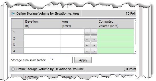
The following data columns are provided:
- Elevation
This data column allows the user to manually define the elevation that corresponds to a polyline/polygon area for computing storage. - Area
This data column allows the user to manually define the area for the corresponding elevation and is used to compute the accumulated storage volume.Clicking on the first […] pick button allows the user to select the polyline/polygon from the Map View to define an area.Clicking on the second […] pick button allows the user to manually measure the storage area on the Map View. - Computed Volume
This read-only data column automatically computes the accumulated storage volume as the user enters the elevation and area data.
The right-click context menu of the table displays commands to cut, copy, and paste cells, as well as insert and delete rows to and from the table. In addition, the user can copy the table data to the clipboard or export it as a Microsoft Excel or PDF document.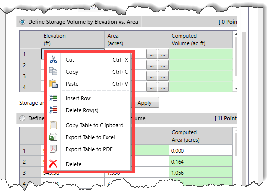
Defining Storage Volume by Elevation vs. Volume
The Define Storage Volume by Elevation vs. Volume radio button section allows the volume of the storage area to be defined by a table of elevations and corresponding accumulated volumes. The Storage volume scale factor entry allows the user to adjust the size of the detention pond storage. When the [Apply] button is clicked, the entered scale factor is multiplied by each entry in the Volume column. Select the Define Storage Volume by Elevation vs. Volume radio button to enable this section.
The following data columns are provided:
- Elevation
This data column is used to define the elevation that corresponds to an accumulated storage volume for computing storage area. - Volume
This data column is used to define the accumulated storage volume for the corresponding elevation and is used to compute the storage area. Note that the first row of this column is read-only and has a default value of 0.00. - Computed Area
This data column automatically computes the area as the user enters the elevation and volume data. Note that the first row of this column is defined by the user and has a default value of 0.00. The remaining cells of this data column are read-only and computed by the software.
Connections
This data panel displays the connections to and from the current storage area. It provides a central location that lists all of the connections with the current storage area.
The following sections describe the Connections data panel:
SA/2D Connections
This section provides a table listing all of the SA/2D connections linked to the current storage area.
The following data columns are provided:
- SA/2D Connection ID
This read-only column lists the ID of the connected SA/2D connection. - Structure Type
This read-only column lists the type of SA/2D connection that is being used. The following SA/2D connection types are available:- Weir
- Weir and Culverts
- Weir and Gates
- Linear Routing
- Connection Definition
This column details the SA/2D connection. Click the [Pick] button to select the SA/2D connection from the Map View. Note that if the selected SA/2D connection already exists in a different row within the table, the following informational dialog box will be displayed.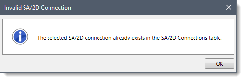
In addition, a [Define] button is provided that allows the user to jump to where the SA/2D connection is defined. Clicking on the [Define] button closes the Storage Area Data dialog box and displays the SA/2D Connections Data dialog box, providing detailed information about the selected SA/2D connection. Refer to this article in our knowledge base to learn more about the SA/2D Connections Data dialog box.
River Reach End Connections
This section provides a table listing the river reaches connected to the current storage area.
The following data columns are provided:
- River & Reach
These two read-only columns list the river and corresponding reach that is connected to the selected storage area. - Cross Section River Station
This read-only column details the cross section river station that is connected to the storage area. Click the [Pick] button to select the river reach that connects to the storage area from the Map View. Note that if the selected river reach already exists in a different row within the table, the following informational dialog box will be displayed.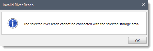
In addition, a [Define] button is provided that allows the user to jump to where the cross section is defined. Clicking on the [Define] button closes the Storage Area Data dialog box and displays the Cross Section Data dialog box, providing detailed information about the selected cross section. Refer to this article in our knowledge base to learn more about the Cross Section Data dialog box.
Lateral Structure Connections
This section provides a table listing the lateral structures connected to the current storage area.
The following data columns are provided:
- River & Reach
These two read-only columns list the river and corresponding reach that is connected to the storage area. - Headwater River Station
This read-only column details the lateral structure headwater river station that is connected to the storage area. Click the [Pick] button to select the lateral structure that connects to the storage area from the Map View.Note that if the selected lateral structure already exists in a different row within the table, the following informational dialog box will be displayed.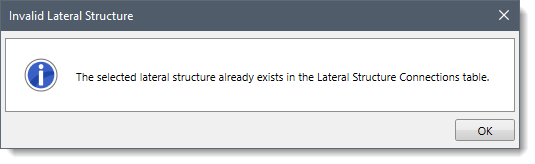
In addition, a [Define] button is provided that allows the user to jump to where the lateral structure is defined. Clicking on the [Define] button closes the Storage Area Data dialog box and displays the Lateral Structure Data dialog box, providing detailed information about the selected lateral structure. Refer to this article in our knowledge base to learn more about the Lateral Structure Data dialog box.
Boundary Conditions
This panel provides a table listing all of the boundary condition lines linked to the current storage area.
The following data columns are provided:
- Boundary Condition ID
This read-only column lists the ID of the connected boundary condition lines. Clicking the pencil icon adjacent to the column allows the user to edit the name of the boundary condition lines.
- Boundary Connection Definition
This column details the boundary condition lines. The following details are provided in this entry based upon the selected boundary condition types.
- Normal Depth
- Water Surface Elev
- Critical Depth
- Rating Curve
- Flow Hydrograph
- Stage Hydrograph
- Stage/Flow Hydrograph
- Lateral Inflow Hydrograph
- Groundwater Interflow
- Precipitation Hydrograph
- Time Series Gate Openings
In addition, a [Define] button is provided that allows the user to jump to where the boundary condition line is defined. Clicking on the [Define] button closes the Storage Area Data dialog box and displays the Unsteady Flow Data dialog box, providing detailed information about the selected boundary conditions. Refer to this article in our knowledge base to learn more about the Unsteady Flow Data dialog box.