The process of georeferencing a pipe to the Map View can be a trial and error process—especially when the exact location of the original pipe is not known. The Georeference Pipes command of GeoSTORM software allows the user to manually georeference each of the pipes to the background base map displayed on the Map View.
Note that a CRS should be assigned before running this command. Otherwise, the software will display the below informational dialog box.
Refer to this article in our knowledge base to learn how to assign a coordinate reference system to a project.
Follow the steps below to use the Georeference Pipes command:
- From the Input ribbon menu, click on Stormwater Pipes dropdown menu and select the Georeference Pipes command.

- The Georeference Pipes dialog box will be displayed.
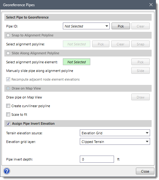
The following sections describe how to georeference an existing pipe and interact with the above dialog box.
Selecting Pipe to Georeference
The Select Pipe to Georeference section allows the user to interactively select the pipe to georeference.
Follow the steps below to select the pipe to be georeferenced:
- Select the pipe from the Pipe ID dropdown combo box that lists all the pipes contained within the project.
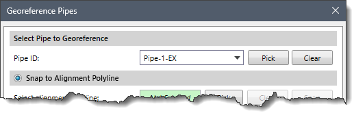
- Alternatively, the user can click the [Pick] button to select the pipe from the Map View. On clicking the [Pick] button, the Georeference Pipes dialog box will temporarily disappear, and a prompt will be displayed on the status bar instructing the user to select the pipe from the Map View.
- Upon selecting the pipe, the Georeference Pipes dialog box will be redisplayed, and the selected pipe will be highlighted on the Map View.
Notes:- The user can select only one pipe at a time.
- The user can click the [Clear] button to cancel all the previous selections and redo the entire process.
- If the model contains a single pipe, then it will be automatically displayed as selected in the Pipe ID dropdown combo box.
Once the pipe has been selected, the user can select among the following georeferencing options:
- Snap to Alignment Polyline
- Slide Along Alignment Polyline
- Draw on Map View
Snapping Pipe to an Alignment Polyline
If an existing alignment polyline for the pipe exists on the Map View, the Snap to Alignment Polyline georeferencing option can be used to snap the pipe to the alignment polyline.
Follow the steps below to use the Snap to Alignment Polyline georeferencing option:
- Select the Snap to Alignment Polyline radio button option to enable this section.
- Click the [Pick] button next to the Select alignment polyline read-only field.
![[Pick] button](https://knowledge.civilgeo.com/wp-content/uploads/2025/12/Georeference-Pipes-Img-5.png)
- The Georeference Pipes dialog box will temporarily disappear, and a prompt will be displayed on the status bar instructing the user to select the alignment polyline from the Map View.
- After selecting the alignment polyline, the dialog box will be redisplayed and the status of the Select alignment polyline read-only field will be changed from Not Selected to Selected. The user can click the [Clear] button to cancel all the previous selections and redo the entire process.
- After selecting the alignment polyline, click the [Snap] button. The software will then snap the selected pipe to the alignment polyline.
![[Snap] button](https://knowledge.civilgeo.com/wp-content/uploads/2025/12/Georeference-Pipes-Img-6.png)
Sliding Pipe Along Alignment Polyline
If a pipe has been snapped to an alignment polyline on the Map View but is not precisely located where it should be, the Slide Along Alignment Polyline georeferencing option can be used to slide the pipe along the alignment polyline.
Follow the steps below to use the Slide Along Alignment Polyline georeferencing option:
- Select the Slide Along Alignment Polyline radio button option to enable this section.
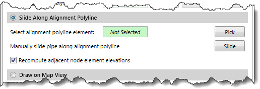
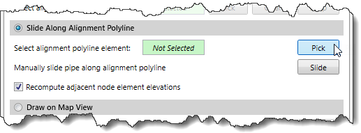
- Click the [Pick] button next to the Select alignment polyline element read-only field.
- The Georeference Pipes dialog box will temporarily disappear, and a prompt will be displayed on the status bar instructing the user to select an alignment polyline from the Map View.
- After selecting the alignment polyline, the following Snap Entity dialog box will be displayed. Click the [Yes] button to snap the entity on the selected polyline or click the [No] button to abort the selection.

- Once the alignment polyline is selected, click the [Slide] button from the redisplayed Georeference Pipes dialog box.
![[Slide] button](https://knowledge.civilgeo.com/wp-content/uploads/2025/12/Georeference-Pipes-Img-10.png)
- The Georeference Pipes dialog box temporarily disappears, and a prompt will be displayed on the status bar instructing the user to select the pipe and drag it along the underlying alignment polyline.
- Click and drag the pipe on the Map View to revise its alignment.
- When finished, press the [Enter] key or right-click and select Done from the displayed context menu. The Georeference Pipes dialog box will be redisplayed, and the pipe will be placed at the new location.
- The user can also check the Recompute adjacent node element elevations checkbox option to recompute the elevation of the adjacent node type elements while georeferencing the pipe. By default, this checkbox is checked.
Note that if the endpoints of the pipe do not overlay the same continuous alignment polyline, then the following informational dialog box will be displayed.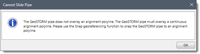
Drawing Pipe on Map View
The Draw on Map View georeferencing option allows the user to draw an alignment polyline on the Map View and automatically snap the selected pipe to the drawn polyline.
Follow the steps below to use the Draw on Map View georeferencing option:
- Select the Draw on Map View radio button option and click the [Draw] button.

- The Georeference Pipes dialog box will temporarily disappear, and a prompt will be displayed on the status bar instructing the user to draw an alignment polyline on the Map View.
- Once the alignment polyline is drawn on the Map View, press the [Enter] key or right-click and choose Done from the displayed context menu.
- The Georeference Pipes dialog box will be redisplayed, and the pipe will then automatically snap to the drawn alignment polyline.
Notes:- The user can turn on the Create curvilinear polyline checkbox option to draw the polyline using a curvilinear segment. Refer to this article in our knowledge base to learn more about element digitizing on the Map View.
- The user can turn on the Scale to fit checkbox option to scale the pipe to fit within the alignment polyline.
Assigning Pipe Invert Elevation
The user can check the Assign Pipe Invert Elevation checkbox option to assign an invert elevation to the georeferenced pipe using a terrain model. The options under this section must be defined before georeferencing pipes so that the invert elevation can be assigned.
For assigning invert elevation, the Terrain elevation source dropdown combo box supports the following surface types:
- CAD Drawing
- Elevation Grid
- GIS Contours
- LandXML Data
- Terrain Surface
- TIN Surface
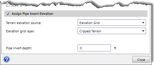
Depending upon the elevation data source type selected, different options are provided to specify additional elevation data information. The user can define an invert depth using the Pipe invert depth entry field to raise or lower the invert of the pipe by the specified amount. A negative invert depth value lowers the pipe by the specified amount.