In modern stormwater management systems, structural components such as manholes, junctions, conduits, and outlets are used to direct the flow. However, these structures often introduce energy losses that impact the system’s performance. These losses are collectively referred to as structural losses or, broadly, head losses.
GeoSTORM, which is based on EPA SWMM (Storm Water Management Model), incorporates detailed loss computations through defined coefficients applied at various structural components. Accurately computing and modeling these losses is essential for predicting flow depths, velocities, and potential surcharges.
This article outlines the structure losses and explains how they are calculated in EPA SWMM. Note that these losses are also available in GeoSTORM.
Types of Losses in EPA SWMM
EPA SWMM primarily considers two types of losses:
- Major Losses
- Minor Losses
Major Losses
Major losses refer to the energy loss resulting from friction between the fluid and the interior surface of the conduit (pipe, culvert, etc.) as the flow moves along its length.
The following factors have an impact on the major losses:
- Pipe length
- Internal pipe friction
- Flow velocity
Major losses in EPA SWMM are typically calculated using the following Darcy-Weisbach equation:
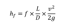
Where:
- hf = head loss due to friction
- f = Darcy friction factor
- L = pipe length
- D = pipe diameter
- v = flow velocity
- g = gravitational acceleration
Minor Losses
Minor losses refer to the energy loss resulting from rapid changes in the magnitude or direction of the flow velocity. These losses can occur at bends, contractions, or enlargements in pipe geometry. Additionally, they are also associated with flows entering a pipe from a larger water body (entrance losses) or flows exiting a conduit to a larger water body (exit losses).
The following factors have an impact on the minor losses:
- Entrance or exit of pipes
- Junctions or manholes
- Bends and elbows
- Expansions and contractions of cross-sectional area
Minor losses in the EPA SWMM are typically calculated using the following Minor Loss equation: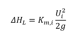
Where:
- ΔHL= minor head loss
- Km,i = loss coefficient
- Ui = flow velocity
- g = gravitational acceleration
Junction Head Losses
Among the primary structural components, minor losses often occur at junctions. Junction head losses refer to the loss of hydraulic head due to sudden changes in flow direction, velocity, or pipe size.
EPA SWMM considers the following minor losses to calculate the head loss at junctions:
- Entrance losses: Result from flow entering a pipe abruptly, often from a manhole or inlet.
- Exit losses: Result from flow exiting a pipe abruptly into another structure or open system, often through an outfall or outlet.
- Average losses: Result from sudden changes in pipe diameter or cross-sectional area (expansion or contraction losses). These losses also include bend losses, which are often caused by sharp changes in flow direction within a pipe network.
Note that in EPA SWMM, the junction head losses are computed internally, with calculations dependent on defined loss coefficients. The user needs to manually assign the minor loss coefficient to calculate the total head loss. Once the user assigns a minor loss coefficient, the software computes the junction head loss using the following equation: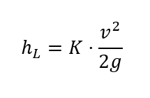
Where:
- hL = head loss at the junction
- K = minor loss coefficient assigned to the junction
- v = velocity of incoming/outgoing flow
- g = gravitational acceleration
Handling Structure Losses in GeoSTORM
In GeoSTORM, the user can manually assign minor loss coefficients to compute the head loss. However, the computed head loss is not displayed to the users and is utilized by the software to compute other modeling parameters.
For example, the user can assign the minor loss coefficients in the Pipe Data dialog box to calculate the head loss and other pipe data results.
Refer to this article in our knowledge base to learn more about the Pipe Data dialog box.
Comparison of Structure Loss Computations in GeoSTORM with Other Software
Other stormwater modeling software, such as StormCAD, use different methods and approaches to compute the structure losses. The following table compares structure loss computations in GeoSTORM (EPA SWMM-based) with StormCAD:
| Feature | GeoSTORM (EPA SWMM-based) | StormCAD (Bentley Systems) |
|---|---|---|
| Underlying Engine | Uses EPA SWMM’s dynamic wave solver, solving the full St. Venant equations. Minor losses are applied only when physically justified, ensuring hydraulically rigorous results. | Uses Bentley’s GVF Rational solver, a simplified method mainly suited for planning/design. Losses are based on predefined methods (HEC-22, AASHTO, etc.), not full dynamic equations. |
| Structure Loss Types | The user can define losses at junctions, entrances, exits, bends, and transitions with customizable coefficients. | Limited to predefined loss types such as junctions, bends, entrances/exits, plus specific cases like plunging and benching. |
| Loss Calculation Method | Applies a single standard formula: Users have full control by directly setting coefficients. | Offers five methods (Standard, HEC-22, AASHTO, Generic, Absolute), but these rely on built-in assumptions and defaults that may not reflect site conditions accurately. |
| Loss Coefficient Input | The user can directly input coefficient values for each structure, allowing precise calibration with field data. | Coefficient values auto-populate based on method/geometry, leading to limited flexibility, and reliance on lookup tables may introduce generalization errors. |
| Bend Angles and Benching | Explicitly modeled by the user by adjusting coefficient values. This allows accurate calibration for bend losses and flexibility to represent non-standard or innovative junction designs, including benching configurations. | Auto-adjusted using HEC-22/AASHTO tables. Bend and benching effects are included, but customization is limited since the factors are fixed and assume standardized conditions. |
| Visualization | Integrates SWMM’s energy profile plots, input forms, and result visualization, ensuring transparency between data and outcomes. Additionally, GeoSTORM also generates comprehensive and customizable reports. | Provides built-in reports and visualization but is tied to internal solver methods. |
| Typical Use Cases | Best for detailed modeling, research, and calibration, where control and hydraulic rigor are required. | Best for design-phase checks under HEC-22/AASHTO standards, less adaptable for advanced studies. |
When modeling junction energy losses, GeoSTORM offers a more robust and adaptable approach than other software, like StormCAD.
GeoSTORM uses SWMM’s dynamic wave solver to solve the full St. Venant equations, delivering physically consistent and hydraulically rigorous results. The user can directly set loss coefficients for junctions, bends, entrances, exits, and transitions, enabling precise calibration with given data. In addition, losses are only applied where necessary in GeoSTORM, ensuring the accuracy of the models.
StormCAD, by contrast, relies on the GVF Rational solver and standardized methods. While this is convenient for design-phase evaluations, it limits flexibility and user control compared to GeoSTORM.