GeoSTORM allows the user to draw or assign a polyline for each subbasin to function as the overland flow path for computing the SCS TR 55 Time of Concentration/Lag Time.
Lag Time and Time of Concentration (TOC) are two related but different concepts used in hydrology computations. Both represent the time required for runoff to travel from the hydraulically most distant point in the watershed to the outlet. This point has the longest travel time—not necessarily the longest physical distance—to the watershed outlet. It is a function of the topography, hydrologic soil type, and land use within the subbasin.
There are many different methods for computing Lag Time and Time of Concentration, but generally, these computations depend on the slope, subbasin characteristics and flow path.
The flow paths can be defined by either drawing or assigning the polyline using the following commands:
- Draw Flow Paths
- Assign Flow Paths
Draw Flow Paths Command
The Draw Flow Paths command allows the user to draw a polyline on the Map View to be used as a subbasin flow path line for computing the TOC/Lag Time.
Follow the steps below to use the Draw Flow Paths command:
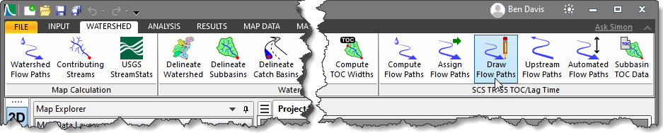
- From the Watershed ribbon menu, select the Draw Flow Paths command.
- The Draw Flow Paths dialog box will be displayed.
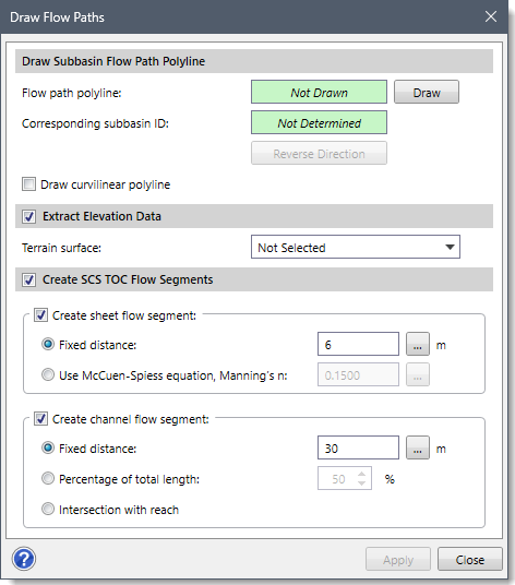
The following sections describe how to interact with the above dialog box.
Drawing a Subbasin Flow Path Polyline
The Draw Subbasin Flow Path Polyline section allows the user to draw a polyline on the Map View as a flow path.
Follow the steps below to draw a flow path polyline:
- Click the [Draw] button and the dialog box will temporarily disappear.

- The status bar (shown under the Map View) will prompt the user to draw a flow path polyline on the Map View in the upstream to the downstream direction.
Note that the software will check whether the drawn flow path polyline is contained within the corresponding subbasin polygon. If not, then the following informational dialog box will be displayed.
- After drawing the flow path polyline, press the [Enter] key or right-click and select Done from the displayed context menu.
- The Draw Flow Paths dialog box will be redisplayed, and the Flow path polyline read-only field will be changed from Not Drawn to Drawn.

The software also determines which subbasin the flow path line corresponds to and displays the subbasin ID in the Corresponding subbasin ID read-only field.
Notes:
- If the “Draw curvilinear polyline” checkbox is checked, then it allows the user to draw curvilinear polyline segments for the flow paths.
- The [Reverse Direction] button reverses the assigned flow direction of the flow path polyline drawn.
Extracting Elevation Data
The Extract Elevation Data section allows the user to extract elevation from the defined terrain surface.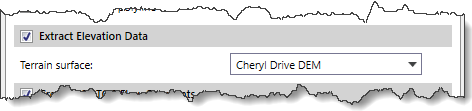
The Terrain surface dropdown combo box only lists elevation grids (i.e., DEMs) available in the project.
Note: Make certain to check the checkbox next to the Extract Elevation Data section header to enable the options within this section.
Creating SCS TOC Flow Segments
The Create SCS TOC Flow Segments section allows the user to subdivide the assigned flow path into flow segments.
Notes:
- If the Create SCS TOC Flow Segments checkbox option is unchecked, the options within this section (i.e., Create sheet flow segment and Create channel flow segment) will be disabled.
- The Create SCS TOC Flow Segments section will only be available if the user selects SCS TR-55 TOC from the Subbasin – TOC/Lag Time Method dropdown combo box on the Options backstage page. Otherwise, if the user selects FAA TOC or SCS Watershed Lag TOC, this section will not be displayed and becomes unavailable from the dialog box.
The following subsections are available in this section:
- Create sheet flow segment
- Create channel flow segment
Create sheet flow segment
This subsection specifies that there is a sheet flow segment at the upstream end of the selected TOC flow path.
The following different ways of computing the sheet flow segment are provided within this subsection:
- Fixed distance
This entry allows the user to specify the length to use for the sheet flow segment. By default, the software uses a segment length of 20 ft (or 6 meters). The user can enter a different value or click the […] Measure button to measure sheet flow length from the Map View. - Use McCuen-Spiess equation, Manning’s n
This entry allows the user to specify Manning’s n roughness value for the software to automatically compute the sheet flow length. The default value of this entry is 0.1500. Alternatively, click the adjacent […] button to measure Manning’s n roughness value from Manning’s Roughness table. This equation is used for post-construction conditions. The sheet flow length is computed using the following equation:
Where,
S = Upstream flow path slope, in ft/ft
n = Sheet flow Manning’s n roughness value
Create channel flow segment
This checkbox option specifies that there is a channel flow segment at the downstream end of the selected TOC flow.
The following different ways of computing the channel flow segment are provided within this option:
- Fixed distance
This entry allows the user to specify the length to use for the channel flow segment. By default, the software uses a segment length of 100 ft (or 30 meters). The user can enter a different value or click the […] Measure button to measure channel flow length from the Map View.
- Percentage of total length
This spin control is used to compute the length of the channel flow segment, based upon a percentage of the total flow path length. This spin control ranges from 1 to 100%, with a default value of 50%.
- Intersection with reach
This option causes the software to compute the channel flow length when the flow path polyline intersects the reach polyline.
Once all the data has been defined in the Draw Flow Paths dialog box, click the [Apply] button. The software will then create a corresponding subbasin flow path line for computing the TOC/Lag Time.
Assign Flow Paths Command
The Assign Flow Paths command allows the user to assign a polyline on the Map View as a subbasin flow path line for computing the TOC / Lag Time.
Follow the steps below to use the Assign Flow Paths command:
- From the Watershed ribbon menu, select the Assign Flow Paths command.

- The Assign Flow Paths dialog box will be displayed.

The following sections describe how to interact with the above dialog box.
Selecting a Subbasin Flow Path Polyline
The Select Subbasin Flow Path Polyline section allows the user to select and assign a polyline on the Map View as a flow path.
Follow the steps below to assign a flow path:
- Click the [Pick] button and the dialog box will temporarily disappear.
![[Pick] Button - Assign Flow Paths Command](https://knowledge.civilgeo.com/wp-content/uploads/2025/04/Draw-and-Assign-Flow-Paths-Command-GeoSTORM-Image-13.png)
- The status bar (shown under the Map View) will prompt the user to click near the downstream end of the already drawn flow path polyline on the Map View to select it.
Note that the software will check whether the assigned flow path polyline is contained within the corresponding subbasin polygon. If not, then the following informational dialog box will be displayed.
- After selecting the flow path polyline, the Assign Flow Paths dialog box will be redisplayed, and the Flow path polyline read-only field will be changed from Not Selected to Selected.

The software also determines which subbasin the flow path line corresponds to and displays the subbasin ID in the Corresponding subbasin ID read-only field.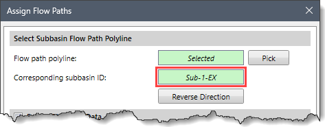
Note that the [Reverse Direction] button reverses the assigned flow direction of the flow path polyline selected.
Extracting Elevation Data
This section is similar to the Extract Elevation Data section as explained above for the Draw Flow Paths command.
Creating SCS TOC Flow Segments
This section is similar to the Create SCS TOC Flow Segments section as explained above for the Draw Flow Paths command.
Once all the data have been defined in the Assign Flow Paths dialog box, click the [Apply] button. The software will then assign the selected polyline as a corresponding subbasin flow path line for computing the TOC / Lag Time.