In GeoHECRAS, the 2D model domain defines the area where two-dimensional (2D) hydraulic computations are performed to simulate how water flows across the land surface. Unlike one-dimensional (1D) modeling (where flow is calculated along a predefined path, such as river centerlines), 2D modeling captures flow in all directions over the terrain.
The 2D model domain is represented by a closed polygon that outlines the study area. Accurately defining this polygon is critical for computing water depths, velocities, and other hydraulic parameters across the floodplain or study area.
The image below shows an example of a 2D model domain defined in GeoHECRAS.
Steps to Define a 2D Model Domain
Follow the steps below to define a 2D model domain in GeoHECRAS.
Assigning the Coordinate Reference System (CRS)
The Coordinate Reference System (CRS) ensures all spatial data layers, including terrain and base maps, are correctly georeferenced within the project. Before creating a 2D model domain, the project’s CRS must be defined. The user can assign the CRS using the Map Coordinates option from the File ribbon menu. Refer to this article in our knowledge base to learn more about the coordinate reference system.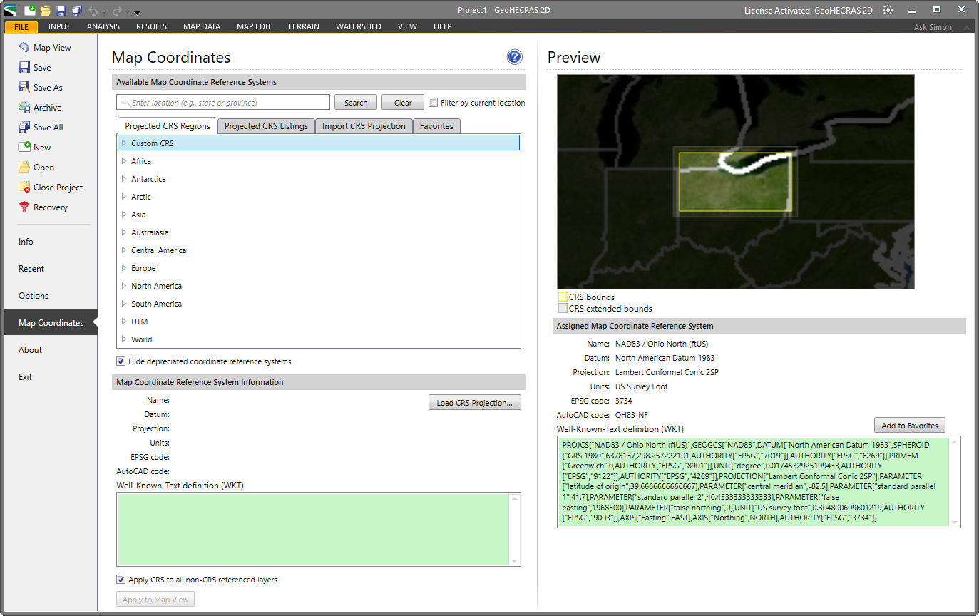
Adding a Base Map Layer
A base map provides high-quality background aerial and other imagery to visualize the terrain and land features. The user can add a base map layer using the Add Base Map Layer command from the Map Data ribbon menu. Refer to this article in our knowledge base to learn more about the Add Base Map Layer command.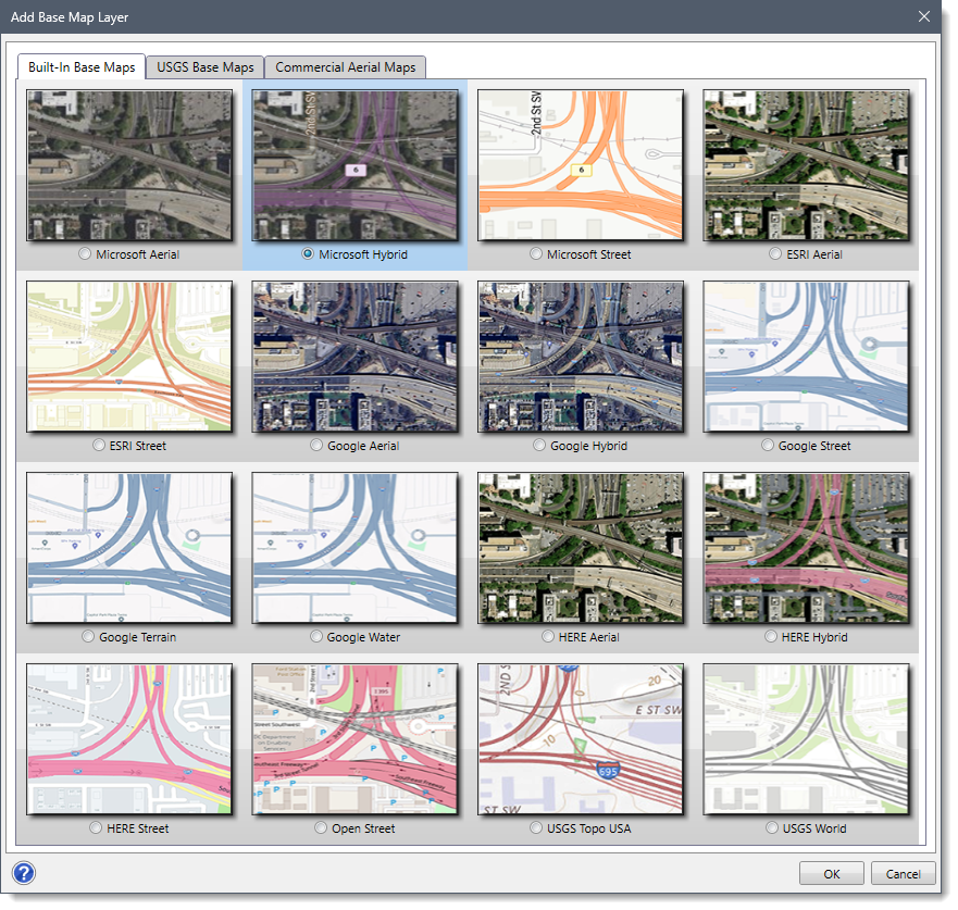
Generating the Terrain Surface
A terrain surface is required to perform 2D flow computations. The user can create a terrain surface using the Generate Terrain command from the Terrain ribbon menu. This command allows the user to import elevation datasets such as DEMs, TINs, or LIDAR data. The terrain is stored in a raster format (.hdf file), which is used for mesh generation and flow calculations. Note that the terrain data covers the entire study area and is in the same CRS as the project. Refer to this article in our knowledge base to learn more about the Generate Terrain command.
Drawing the 2D Flow Area
After generating the terrain surface, define the region for the 2D flow simulation by drawing a polygon that represents the outer boundary of the 2D model domain. When outlining the polygon, ensure it covers the main channel, floodplain boundaries, and any other areas likely to be affected by flooding. Avoid including unnecessarily large regions, as this increases computational time without improving accuracy. The user can draw the 2D flow area using the Draw 2D Flow Areas command from the Input ribbon menu. Refer to this article in our knowledge base to learn more about the Draw 2D Flow Areas command.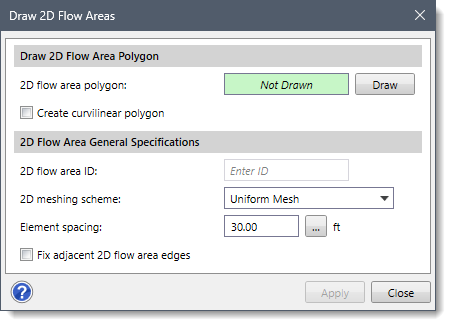
Defining Upstream and Downstream Boundaries
After defining the 2D flow area polygon, specify the boundary conditions that allow water to enter and exit the 2D model domain. This is typically done by drawing upstream and downstream boundary polylines using the Draw Polylines command from the Map Edit ribbon menu. These polylines will later be assigned flow hydrographs, stage hydrographs, or normal depth conditions depending on the modeling requirements.
Refining the Computational Mesh
After defining the upstream and downstream boundaries, generate and refine the computational mesh for 2D flow calculations. The user can generate a computational mesh using the Draw 2D Mesh Zones command from the Input ribbon menu. Refer to this article in our knowledge base to learn more about the Draw 2D Mesh Zones command.
Once the mesh is generated, it can be refined by adjusting cell sizes or adding breaklines to align the mesh with terrain features such as levees, channels, or roads. These refinements help improve the accuracy of flow simulations. Refer to this article in our knowledge base to learn how to refine the mesh within the 2D flow area boundary.
Saving the Project
After refining the mesh, save the project. To do this, click the Save option from the File ribbon menu or press CTRL + S on the keyboard. If the project has not yet been named, the software will display a Save As dialog box to name and save the project. Saving the project stores all edits made to the 2D model domain, including flow areas, boundary conditions, and mesh configurations.
Running the Analysis
Finally, run the project analysis using the Compute Unsteady – Current Scenario command from the Analysis ribbon menu. During the simulation, GeoHECRAS uses the defined 2D model domain and mesh to compute water surface elevations and flow velocities within the specified area. Refer to this article in our knowledge base to learn more about the Compute Unsteady – Current Scenario command.