
Welcome to CivilGEO Knowledge Base
Welcome to CivilGEO Knowledge Base
The Upstream Flow Paths command can be used to compute and trace the upstream overland flow path from a user-defined terminus point(s) to a point of intersection with the current subbasin upstream boundary.
This command is also useful in determining the longest flow path from anywhere within the subbasin, which can then be used to define the TOC (Time of Concentration) or Lag Time flow path for the subbasin. However, the true TOC flow path may not be obvious for various reasons and using this command alone may be insufficient to represent the situation on the ground. There may be roadways, bridges, culverts, buildings, and other manmade and natural obstructions that may alter the actual TOC flow path of a subbasin, but which may not be immediately apparent from the elevation grid. However, the user can piece together a true representative TOC flow path by using parts of the upstream flow paths created using this command, raindrop flow paths, and manually-digitized flow lines where obstructions exist. Refer to this article to learn more about the Automated Flow Paths command.
To use the Upstream Flow Paths command, follow these steps:


The following sections describe how to use the Upstream Flow Paths command and interact with the above dialog box.
In this section, the user can select the elevation terrain surface from the Terrain surface dropdown combo box, which lists the terrain surface(s) present in the project. By default, the terrain surface selected in the Scenario Manager dialog box will be selected in the Terrain Surface dropdown combo box.
The Select HEC-HMS Subbasins to Compute Flow Paths section controls which subbasins should have the longest flow paths computed. The section contains both All subbasins and Select subbasins options.

The All subbasins entry causes the software to compute the longest flow paths for all subbasins within the HEC-HMS layer.
The Select subbasins entry allows the user to interactively select subbasin polygons from the HEC-HMS layer on the Map View. Clicking the [Pick] button will cause the dialog box to temporarily disappear and will allow the user to select HEC-HMS subbasin polygons from the Map View. The total number of selected subbasin polygons will be displayed in the adjacent read-only entry upon return to the dialog box.
Note that the Upstream Flow Paths command confirms that the selected subbasins overlay the selected elevation grid terrain surface. If not, the software will display the following messages.
If one subbasin was selected:
 If more than one subbasin was selected:

This section is used to select the limits of the terrain surface over which the upstream flow paths will be computed.
 The following options are available to define the extents of the terrain surface processing limits:
In this section, the user can define the name for the layer group in the Layer group name input field.
 This name identifies the layer group that will be created in the Map Data Layers panel and will contain the upstream overland flow paths. The Delete previously computed overland flow paths checkbox can be used to delete any previously computed upstream flow paths. By default, this checkbox is checked.
The Draw Terminus Points section allows the user to draw terminus points. Click the [Draw] button and the dialog box will temporarily disappear, allowing the user to place the terminus point(s) on the Map View.
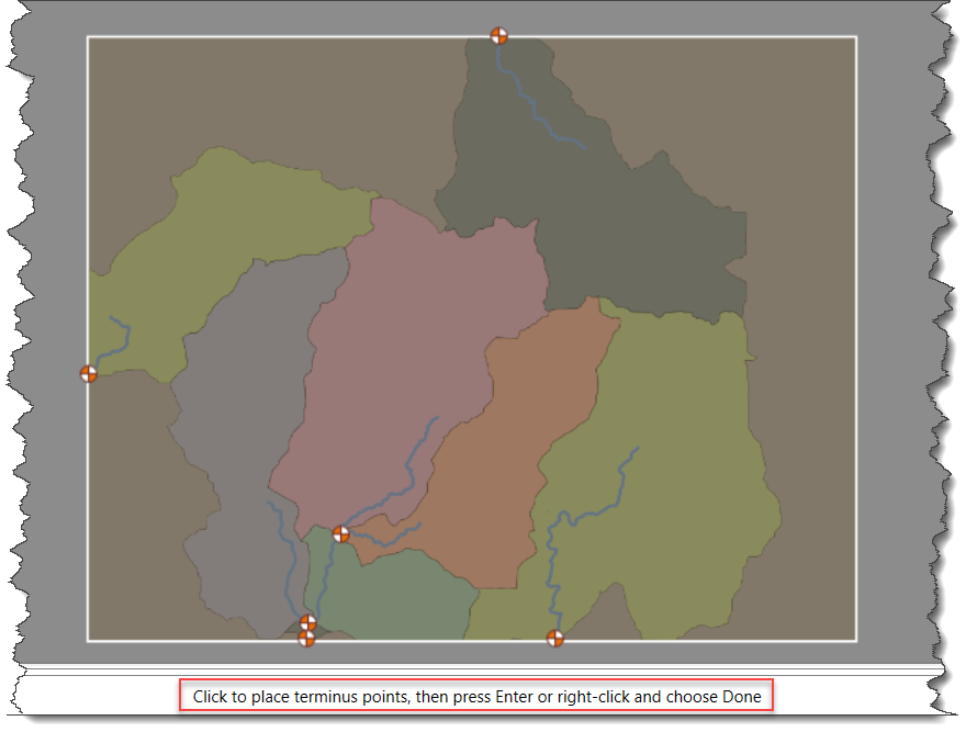
After drawing the terminus points, the dialog box will be redisplayed, and the number of terminus point(s) drawn will be displayed in the Terminus points read-only field.

After defining all the required fields, click the [Compute] button. The Upstream Flow Paths confirmation dialog box will be displayed. Click the [Yes] button to compute the flow direction grid. To cancel the process, click the [No] button.

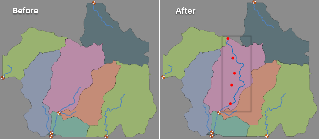
The terminus point(s) and the computed upstream overland flow path will be displayed on the Map View as shown below.
Note that while the computation is running, the [Close] button changes to [Cancel] so that the user can abort the computation process if desired.
Once the upstream flow paths are computed, the Overland Flow Paths layer will be created in the Map Data Layers panel, which contains the Upstream Flow Paths and Terminus layers that reference the computed upstream flow path and selected downstream terminus point.


CivilGEO G2 Reviews
4.8/5.0 Rating, Over 230 Reviews

GeoHECRAS is recognized as the top Civil Engineering Design Software with an average of 4.8 out of 5.0 rating from over 230 real user reviews on G2.


We use cookies to give you the best online experience. By agreeing you accept the use of cookies in accordance with our cookie policy.
When you visit any web site, it may store or retrieve information on your browser, mostly in the form of cookies. Control your personal Cookie Services here.


