The Steady Flow Computational Options command of GeoHECRAS software allows the user to define steady flow computational options and tolerances. The software provides some default computational options and tolerances for 1D steady flow models. The tolerances are used in the solution of steady flow equations. In general, it is recommended that the default computation options and tolerances be maintained. However, the user can override the default computational options to achieve model stability while maintaining computational accuracy. Extra care should be taken while overriding the default calculation tolerances as it could result in computational errors in the water surface profile.
Follow the steps given below to use the Steady Flow Computational Options command:
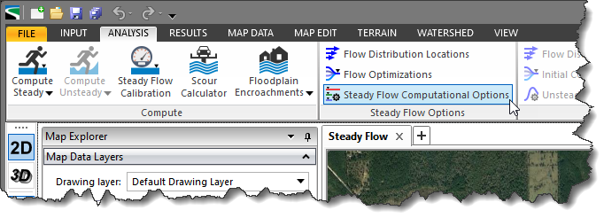
- From the Analysis ribbon menu, select the Steady Flow Computational Options command.
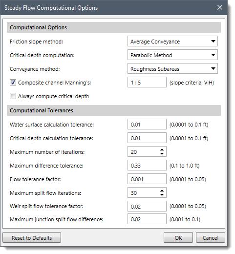
- The Steady Flow Computational Options dialog box will be displayed.
The following sections describe how to interact with the above dialog box.
Computational Options
This section allows the user to select friction slope method, critical depth computation method, and conveyance method from various options.
The following options are provided in the Computational Options section:
Computational Tolerances
This section allows the user to set values for various tolerances. These tolerances are used in the solution of the energy equation.
Note that increasing the default value for tolerances could result in computational errors in the water surface profile.
The following options are provided in the Computational Tolerances section:
- Water surface calculation tolerance: This tolerance value is used to compare against the difference between the computed and assumed water surface elevations. When the difference is less than the tolerance, the software assumes that it has a valid numerical solution. The default value is 0.01.
- Critical depth calculation tolerance: This tolerance value is used during the critical depth solution algorithm. The default value is 0.01.
- Maximum number of iterations: This variable defines the maximum number of iterations that the software will make when attempting to balance a water surface profile. The default value is 20.
- Maximum difference tolerance: This tolerance is used during the balance of the energy equation. As the software attempts to balance the energy equation, the solution with the minimum error (assumed minus computed water surface) is saved. If the software goes to the maximum number of iterations without meeting the specified calculation tolerance, the minimum error solution is checked against the maximum difference tolerance. If the solution at minimum error is less than this value, then the software uses the minimum error solution as the answer, issues a warning statement, and then proceeds with the calculations. If the solution at minimum error is greater than the maximum difference tolerance, then the software issues a warning and defaults the solution to critical depth. The computations then proceed from there. The default value is 0.33.
- Flow tolerance factor: This factor is only used in the bridge and culvert routines. The factor is used when the software attempts to balance weir flow and flow through the structure. The factor is multiplied by the total flow. The resulting value is then used as a flow tolerance for the balance of weir flow and flow through the structure. The default value is 0.001.
- Maximum split flow iterations: This variable defines the maximum number of iterations that the software will use during the split flow optimization calculations. The default value is 30.
- Weir split flow tolerance factor: This tolerance is used when running a split flow optimization with a lateral weir/gated spillway. The split flow optimization continues to run until the estimate of the lateral flow and the computed value are within a percentage of the total flow. The default value for this is 2 percent (.02).
- Maximum junction split flow difference: This tolerance is used during a split flow optimization at a stream junction. The software continues to attempt to balance flow splitting from one reach into two until the energy gradelines of the receiving streams are within the specified tolerance. The default value is 0.02.


