
Welcome to CivilGEO Knowledge Base
Welcome to CivilGEO Knowledge Base
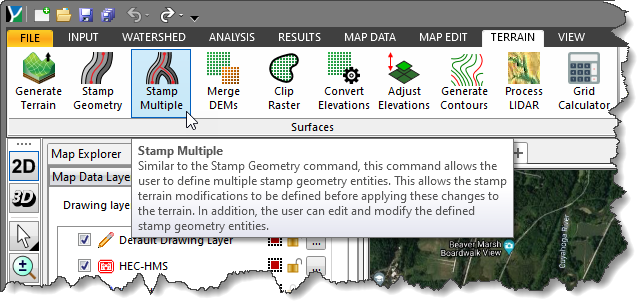
The Stamp Multiple command allows the user to perform bulk stamp geometry operations. Similar to the Stamp Geometry command, this command allows the user to define multiple stamp geometry operations to be applied at one time to the terrain surface. This allows the stamp terrain modifications to be defined before applying the changes to the terrain. To learn more about Stamp Geometry command, refer to this article in our knowledge base.
The Stamp Multiple command is helpful in situations where the user may need to edit the terrain surface multiple times—especially when working with large DEM files where stamping one feature causes the entire terrain surface to be recreated each time.
The command supports various options for defining the stamping operation, including:
The user can specify the merge order of the stamp operations, which will determine the stamp order of the composite terrain surface. In addition, the user can edit and modify the defined stamp geometry entities so that an iterative, trial and error approach can be used in constructing the updated terrain surface.
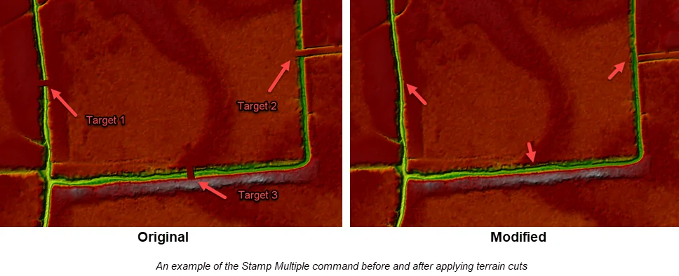
For example, the below image shows three false dams in the running ditch that need to be removed. The Stamp Multiple command can be used to remove all three false dams simultaneously.
 To use the Stamp Multiple command, follow the steps below:
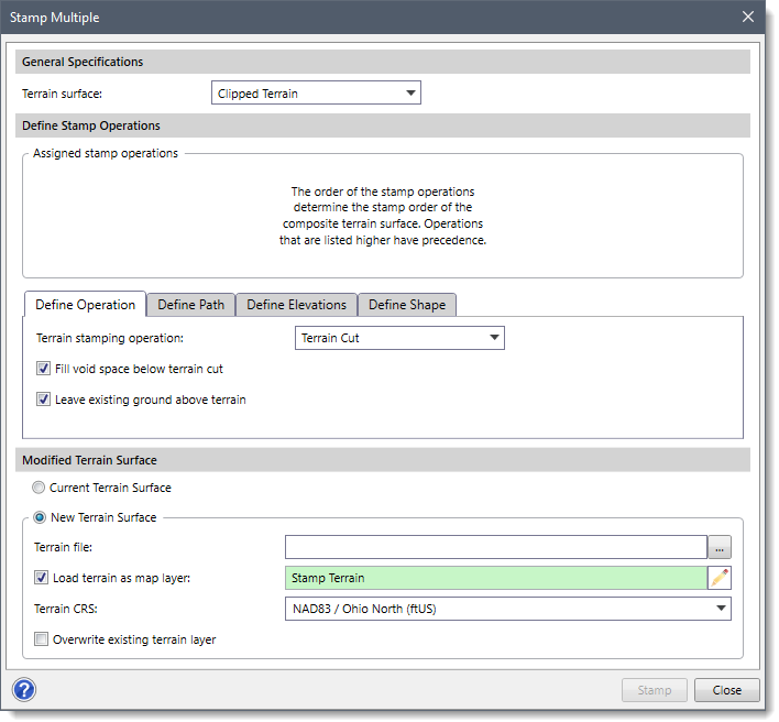
The following sections describe how to use the Stamp Multiple command and interact with the above dialog box.
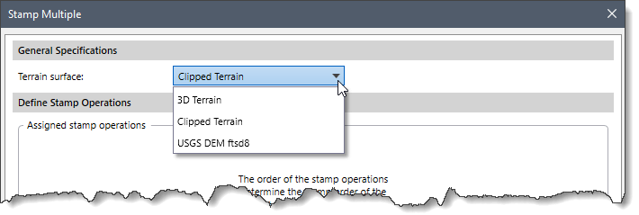
From the Terrain surface dropdown combo box, the user can select a source terrain file from the existing elevation layers within the current project. The elevation layer which is used in extracting cross sections and 2D model elevation data is selected by default.
This section presents a table summarizing the assigned stamp operations. This table appears after the user has defined the terrain interpolation path so that multiple stamp operations can be displayed.
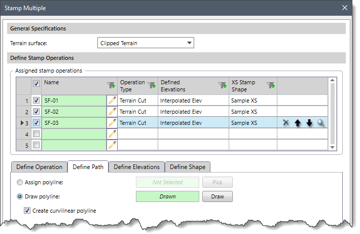 This Assigned stamp operations table displays the list of stamp operations assigned. This table includes the Name, Operation Type, Defined Elevations, and XS Stamp Shape of the assigned stamp operations. In the first column, the user can change the name by clicking on the pencil icon and checking the appropriate checkboxes required for an operation. The last column allows the user to delete, move up/down, or zoom to a particular stamp operation. The user can add additional stamp operations by selecting the next row. The type, elevation, and shape of the corresponding stamp operation can be defined using the following sections:
This section defines the general parameters used to stamp terrain geometry and the type of stamping operation.
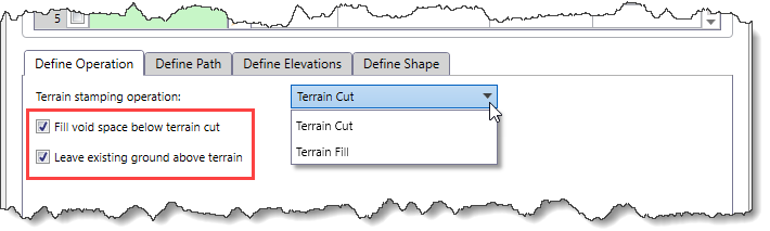 From the Terrain stamping operation dropdown combo box, select the type of stamping operation. The following options are available:
Note that the Fill void space below terrain cut and the Leave existing ground above terrain checkboxes are checked by default. They facilitate creating a more accurate representation of the stamped terrain geometry by daylighting the stamping operation into the source terrain geometry.
This section defines the path to which the terrain surface stamping is to be applied.
There are two options for defining the path:
If there is an existing polyline on the Map View that can be used for the stamping operation, the user can click the [Pick] button adjacent to the Assign polyline radio button and select a polyline from the Map View.
![Define Path - [Pick] button](/wp-content/uploads/sites/25/2023/03/Stamp-Multiple-Command-Imge-7.png) Alternatively, the user can click the [Draw] button adjacent to the Draw polyline radio button to draw a polyline on the Map View.
Alternatively, the user can click the [Draw] button adjacent to the Draw polyline radio button to draw a polyline on the Map View.
![Define Path - [[Draw] button](/wp-content/uploads/sites/25/2023/03/Stamp-Multiple-Command-Imge-8.png) The Create curvilinear polyline checkbox can be used to create a smooth terrain interpolation path while drawing the polyline.
The Create curvilinear polyline checkbox can be used to create a smooth terrain interpolation path while drawing the polyline.
This section defines how the interpolated terrain elevations will be assigned along the polyline path.
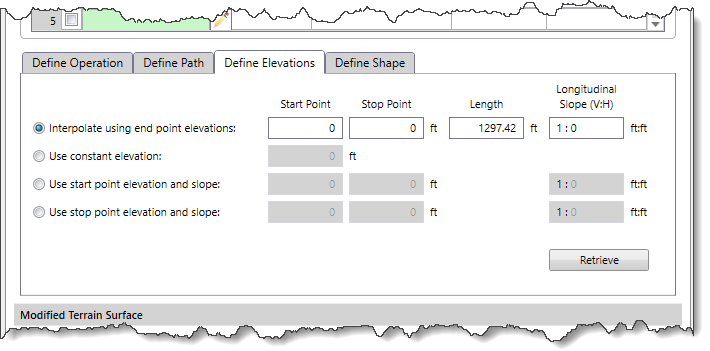 There are four radio button options for defining how the elevations are assigned:
The user can first click the [Retrieve] button to automatically extract the start and end elevation values, length, and slope data for the selected polyline and then choose any of the above options to define the way elevations will be interpolated along polyline paths.
This section defines how the interpolated terrain region will be shaped along the polyline path. There are two options for defining the interpolation path shape. The user can either choose the Use end point terrain geometry or the Use trapezoid geometry option.
![Define Shape - [Pick] button](/wp-content/uploads/sites/25/2023/03/Stamp-Multiple-Command-Imge-10.png)
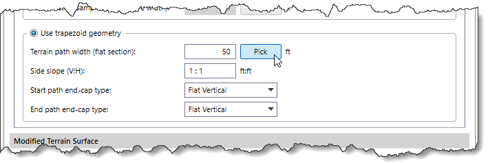 The Side slope (V:H) ratio value is set to 1:1 by default, which corresponds to a 1 ft (m) rise to a 1 ft (m) run. A ratio of 1:0 represents a vertical wall. However, many times a flatter slope is required, such as 1:2 or 1:3. The user can define the ratio to represent the slope.
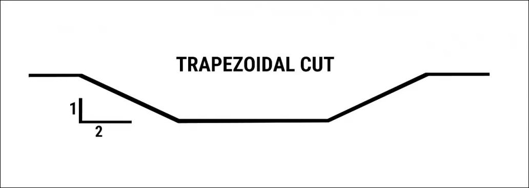
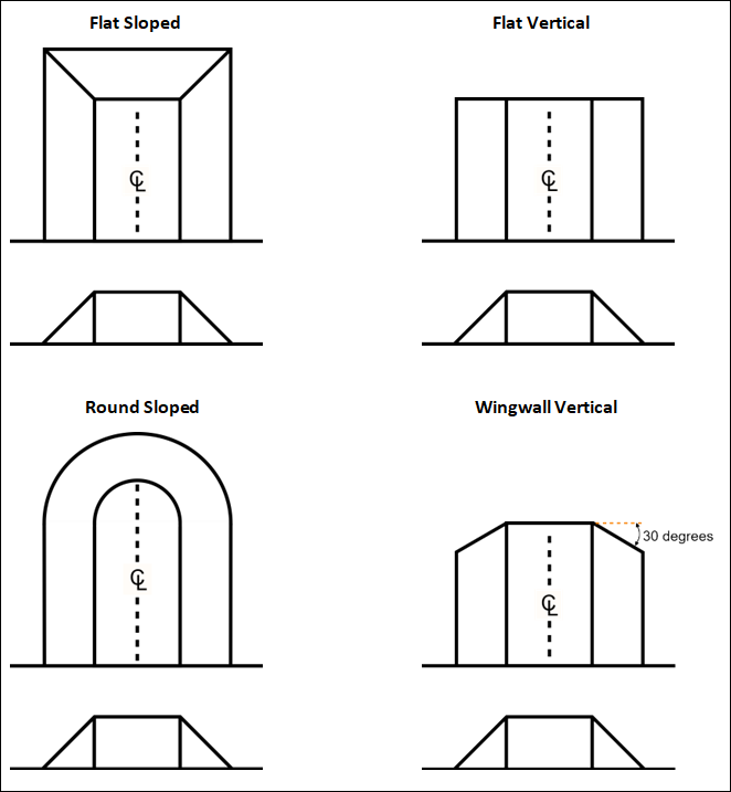
The Start path end-cap type and End path end-cap type dropdown combo boxes allow the user to choose different end cap styles from the following options:
This section is used to define the specifications of the revised terrain grid.
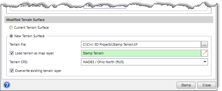
After the options for stamping the terrain geometry have been defined, click the [Stamp] button and the software will generate the revised terrain grid with multiple terrain stamping. In addition, the software loaded the DEM file as a new layer in the Map Data Layers panel.


CivilGEO G2 Reviews
4.8/5.0 Rating, Over 230 Reviews

GeoHECRAS is recognized as the top Civil Engineering Design Software with an average of 4.8 out of 5.0 rating from over 230 real user reviews on G2.


We use cookies to give you the best online experience. By agreeing you accept the use of cookies in accordance with our cookie policy.
When you visit any web site, it may store or retrieve information on your browser, mostly in the form of cookies. Control your personal Cookie Services here.


